21
UC5e IM Rev 2-1 July 2004
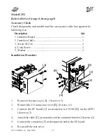
17.
Locate the cable [A] Part No. VU5 05 410, and connect the 26 pin
ribbon cable end to the outer connector on the UC5E main board.
The DB25 end is connected to the DB 25 cut out on the chassis of the
main frame using the two M3 x 5mm jack posts supplied in the IF Kit
Type-10.
18.
Reinstall the MPU Cover, the rear cover and then the upper rear cover
of the Digital Duplicator.
Figure 2e
[A]


