28
UC5e IM Rev 2-1 July 2004
8.
Place the assembled mounting plate [A] onto the standoffs on the chassis
and secure using the three M4 screws [B] set aside in step 4.
9.
Locate a M3 x 10mm standoff and screw it through the mounting plate
into the standoff [C].
10.
Locate the UC5E Main Board, Part No. VU5E 05 200, and secure it by
screwing in a M3 x 6mm screw [D].
CAUTION:
THIS PART IS VERY SENSITIVE TO STATIC. PLEASE EN-
SURE THE CORRECT ANTISTATIC PRECAUTIONS ARE
TAKEN.
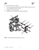
The RAM SIMM [E] should be on the bottom.
11.
Install four "M3 x 25mm female to female standoffs" [F].
Figure 3c
[B]


