INSTRUCTION MANUAL CENTRAL COMMAND STATION MX10, MX10EC Page21
5.
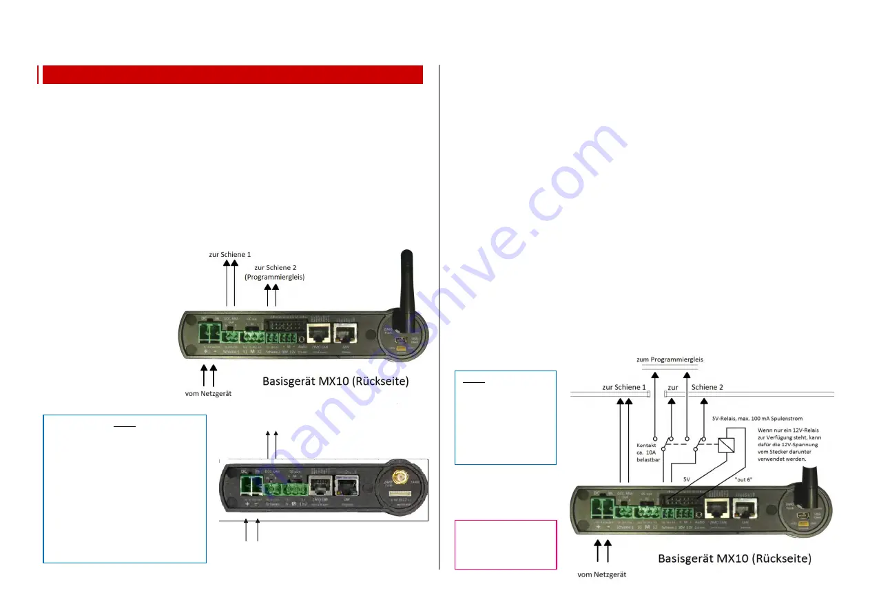
Rail connections, programm. track, AOS in/out
The central command station MX10 is equipped with two rail connections,
MX10EC only has one output:
•
the
output “Schiene 1”
(track 1) - usually to connect the
“main track”
, i.e. the actual layout
•
the
output “Schiene 2”
(track 2) - sometimes used as additional power circuit (with separately
adjustable voltage, maximum current, etc.) or
as
programming track
(addressing and programming decoders in service mode, called
SERV
PROG
), and as
updating track
(to update decoders and to load sound into the decoders).
“Schiene 2” is completely fit for traffic, if it is not occupied by a programming, updating or sound
loading task. It has the same track signal as track 1. If track 2 is used as programming track which
is accessible from the main track, it has to be insulated completely from the main track. Because the
train passes the sectioning points between track 1 and track 2, the polarity (N & P clamps) has to be
the same on both tracks.
•
MX10EC provides the output “Schiene” for the main track and also for the programming
track - depending on the situation.
The running voltages on the track
outputs generally can be adjusted
individually,
see chapter “Main settings”.
each
10 - 24 V
-
(see chapter “Application...”)
and are fully stabilised.
The limitations:
- Track 1:
1 - 12 A
and
Track 2:
1 - 8 A -
as well as
the turn-off times
-
0.1 - 5 sec
each -
(e.g. to bypass
short circuits on
Frogs)
Voltage and maximum current on the programming track in SERVICE MODE (SERV PROG):
By default, the voltage and current values on the programming track are automatically set to 11V
and 0.3 A (maximum current at the beginning) or 0.1 A (maximum current after 100 msec) after enter-
ing in service mode -
usually with a controller by pressing E-key + MN-key. This corresponds to the standard published by
Railcommunity (European association of manufacturers of digital model railway products).
The idea behind these rigid current limits when programming is to prevent damage to vehicles and
electronics, even if for example a decoder is wired incorrectly. Nevertheless, not all vehicles are de-
signed to actually consume such a low amount of power. On the one hand, there are capacitors that
need to be charged, and on the other hand, the locos contain consumers which are not connected to
the decoder and therefore cannot be turned off.
Therefore the possibility to change this default configuration of voltage and current exists; this is done
in:
MX10 main menu
VOLT & AMP DETAIL
SERV: Running voltage, maximum current
The controller shows a WARNING on the SERV PROG screen, if the SERV PROG configurations de-
viate from the standard described above.
Using an external programming track relay:
In case the “track” is used as part of the layout and as programming track,
(at the MX10EC if Service
Mode shall be used at all)
you can switch either manually or by relay, which is more comfortable.
The relay is therefore connected - as shown in the graphic - to the 16-pole pin connector between the
pins “5V” and “out-6”
(at the MX10EC between “5V” and “out-2”)
The relay has to be a type with two
switching contacts which have a minimum load capacity of 5 A, at the best of 10 A.
The MX10 automatically switches the relay, so that it connects “Schiene 2” to the programming track,
while a controller (and therefore the connection point “Schiene 2” or “Schiene”) is in operation state
SERV PROG
. Otherwise the connection “Schiene 2” or “Schiene” is connected to the programming
track, while otherwise it is connected to the layout.
.
NOTE: This is the stand-
ard use of the “out-6” pins.
Nevertheless, this stand-
ard can be changed (see
for example: menu point
DCC SERV PROG config-
urations); be as it is, the
use as programming track
relay would not be availa-
ble.
NOTE:
“Side effects” due to high track current
are kept low in the MX10 and MX10EC
by special measures:
High frequency-sliders for track outputs with
low output capacity
prevent high energy
peaks.
The
spark suppression function
developed
by ZIMO (adjustable in three steps)
suppresses occurring light bows.
- The special configuration
“adaptive over-
current detection”
defines an overcurrent
shutdown due to a sudden current increase,
also when the actual overcurrent threshold is
not yet reached.
MX10EC:
“out-2” pin for the pro-
gramming track relais
(to “5V” pin)!
zur Schiene
(Programmiergleis)
Basisgerät MX10EC (Rückseite)
vom Netzgerät


