SR981S/SR982S operation manual of solar pump station
Page 12 of 85
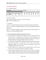
5.2 Terminal connection
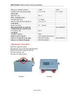
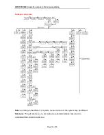
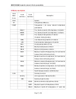
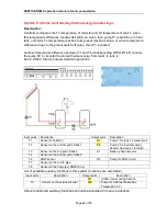
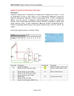
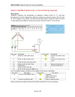
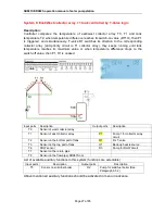
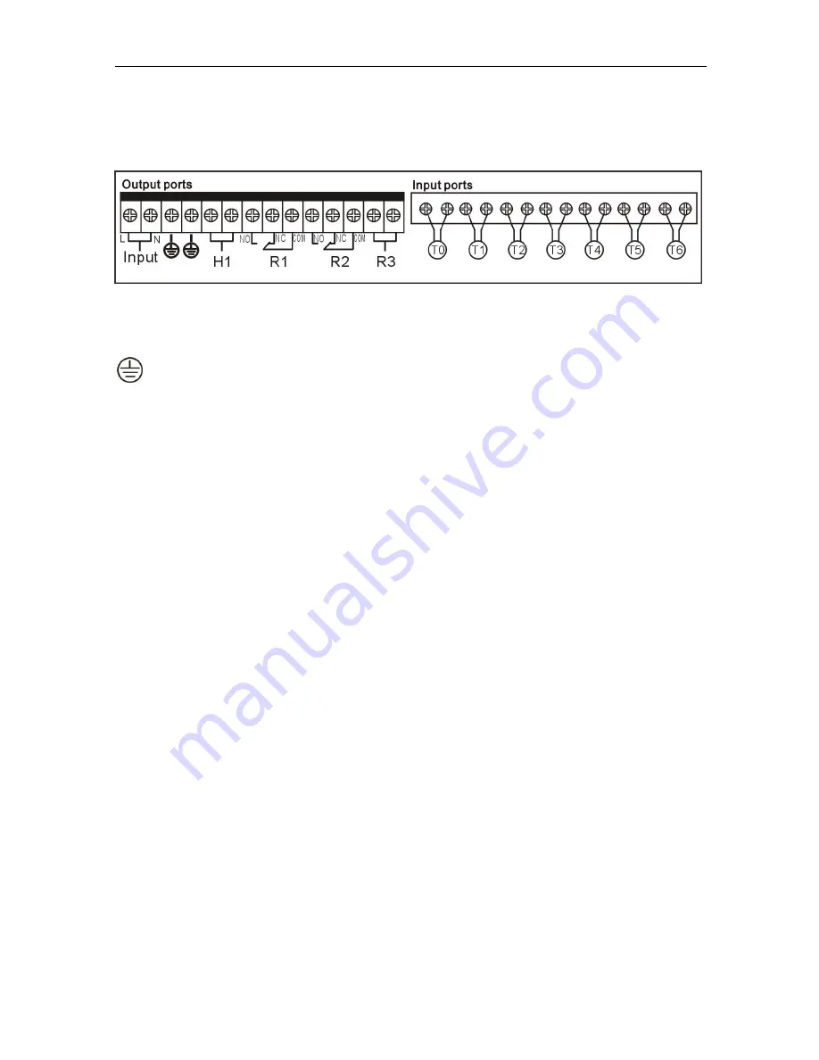
Terminal ports layout
Power connection
Input: for power connection, L is for live wire, N is for neutral line.
is for connection with ground.
Input ports
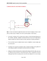
Input T0 ~ T1: PT1000 temperature sensor, for measuring the collector temperature
Input T2
~
T6: NTC10K
,
B=3950 temperature sensor, for measuring tank and pipeline
temperature
Note: T7
、
T8 pipeline temperature sensors have been wired on built controller,so no
position on the input ports(SR981S NO T8).
Advice regarding the installation of temperature sensors:
①
Only original factory equipped Pt1000 temperature sensors are approved for using
with the collector, it is equipped with 1.5meters silicon cable and suitable for all
weather conditions, the cable is temperature resistant up to 280
o
C, not necessary to
distinguish the positive and negative polarity of the sensor connection.
②
Only original factory equipped NTC10K,B=3950 temperature sensors are approved for
using with tank and pipe, it is equipped with 1.5mr PVC cable, and the cable is
temperature resistant up to 105
o
C, not necessary to distinguish the positive and
negative polarity of the sensor connection.
③
All sensor cables carry low voltage, and to avoid inductive effects, must not be laid
close to 230 volt or 400 volt cables (minimum separation of 100mm).
④
If external inductive effects are existed, e.g. from heavy current cables, overhead train
cables, transformer substations, radio and television devices, amateur radio stations,
microwave devices etc, then the cables to the sensors must be adequately shielded.

