SR981S/SR982S operation manual of solar pump station
Page 22 of 85
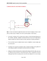
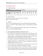
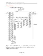
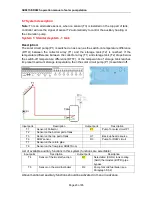
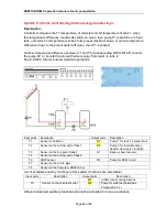
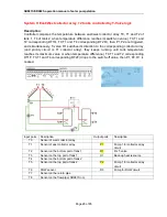
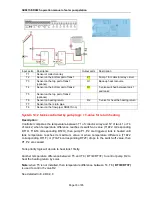
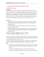
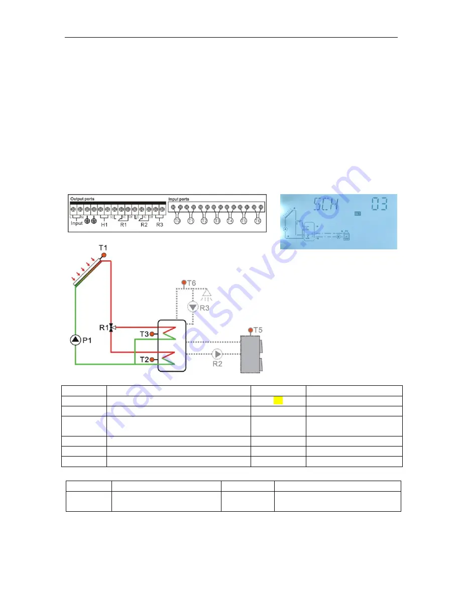
System 3: 1 tank + T-valve to heat tank in layer
Description:
Controller compares the temperature of collector T1 and temperature of tank T2 and T3, if
the temperature difference between collector and tank is over the preset switch-on
temperature difference (T1 & T2 is corresponding DT1O, T1 & T3 is corresponding DT2O),
then pump P1 is switched-on, and simultaneously, T-valve is switched to heat the
corresponding tank part, when the switch-off temperature difference between collector and
part reaches ( T1 & T2 is corresponding DT1F, T1& T3 is corresponding DT2F) or the tank
temperature reaches to its maximum value, then P1,R1 are ceased.
Tank priority logic will decide to heat bottom part of tank firstly.
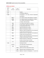
Input ports
Description
Output ports
Description
T1
Sensor of Collector
P1
Pump for solar circuit
T2
Sensor on the bottom part of tank
H1
Back-up heat resource
T3
Sensor on the top part of tank
R1
For T-valve to heat tank
different part
T6
DHW sensor
R3
Pump for DHW circuit
T7
Sensor on the return pipe
T8
Sensor on the flow pipe( SR981S no)
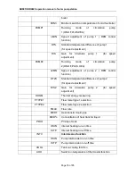
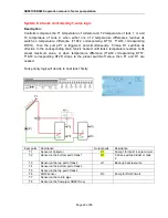
List of available auxiliary functions in this system (functions are selectable)
Input ports
Description
Output ports
Description
T5
Sensor on the solid fuel boiler
R2
Pump for solid fuel boiler(See
Paragraph 8.5.2)
Above mentioned auxiliary functions should be activated in menu in advance.