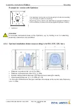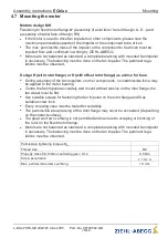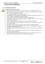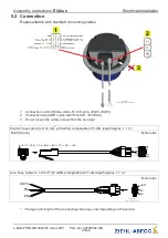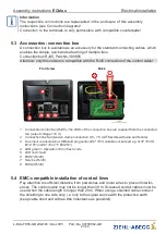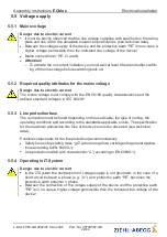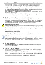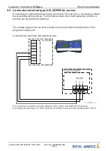
5.11 Open-Collector output
“
A1
”
(status / tacho)
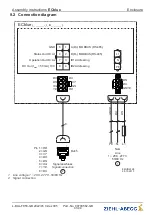
Open-Collector pulse output for status display or speed display.
Status display
(function for factory setting)
Depending on the operating state of the device, the output
“
A1
”
is
switched to GND potential for a certain number of pulses.
The status of the device can be displayed by this digitally coded signal.
With the output voltage
“
10 V
”
, a standard LED / low-power LED can be
controlled by using a pull-up resistor. This lights up if the output
“
A1
Status Out OC
”
(OC = Open-Collector) is on GND potential.
Attention! Observe the maximum
“
10 V
”
output voltage load, see techni-
cal data and connection diagram.
The details of which pull-up resistor needs to be used depend on the
speci
fi
cation on the LED that is used.
Explanation of
fl
ash codes see Diagnostic / Status Out with
fl
ash code.
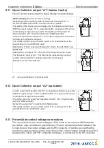
Pull Up
10V
A1
GND
06.11.2013
i_ecblue_a1_status_oc.eps
200...300 Ω
Tacho out
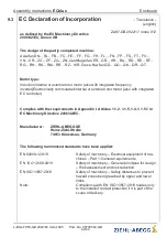
Alternatively, via output
“
A1
”
, the current motor speed can be output.
The frequency (duty cycle 1 : 50) that can be measured by a pull-up
resistor at the output
“
A1
”
corresponds to the motor speed.
Example: 10 Hz x 60 = 600 rpm
Pull Up
10 V
A 1
GND
Hz
n = f x 60
5 kΩ
06.11.2013
i_ecblue_a1_tacho_oc.eps
200...300 Ω
A1
more speci
fi
cations: Technical data!
5.12 Open-Collector output
“
A2
”
(operation)
Via the output
“
A2 Operation Out OC
”
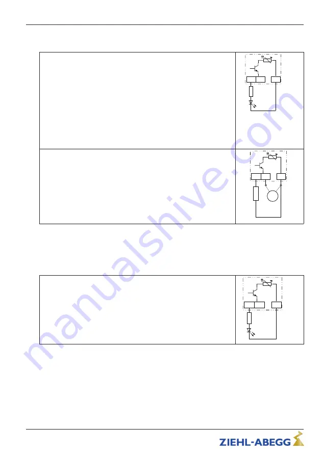
an operating indication is possible.
With the output voltage
“
+10 V
”
a standard LED / low-power LED can be
controlled by using a pull-up resistor.
This lights when the output
“
A2 Operation Out OC
”
(OC = Open-Collec-
tor) is on GND potential.
By fault the output
“
A2
”
is switched to GND potential.
The details of which pull-up resistor needs to be used depend on the
speci
fi
cation on the LED that is used.
Pull Up
10 V
A 2
GND
06.11.2013
i_ecblue_a2_operation_oc.
200...300 Ω
5.13 Potential at control voltage connections
The connections for the control voltage (< 30 V) relate to the common GND potential
(exception: relay contacts are potential-free). There is a potential isolation between the
connections for the control voltage and the PE conductor. It must be ensured that the
maximum external voltage at the connections for the control voltage cannot exceed 30 V
(between the
“
GND
”
and
“
PE
”
conductor terminals). A connection to the PE conductor
Assembly instructions
ECblue
Electrical installation
L-BAL-F056-GB 2022/45 Index 005
Part.-No. 00700562-GB
30/44


