Attention!
•
Avoid structural damage or stress with installation. Flange and mounting bracket must
be
fi
xed
fl
at on a level surface.
•
Provide screwed connections with suitable screw locking.
4.6.3 Erecting the equipment: Design ER.. / GR.. / WR..
•
To avoid the transference of disruptive vibrations, we recommend de-coupling the
entire plug fan to avoid sounds transmitted through solids. (Spring and/or attenuation
units are not a constituent part of the standard scope of delivery). Look at our
catalogue for positioning the decoupling elements or request a dimensions sheet
stating the type designation and Part.-No.
•
Erect in the open air only if this is expressly mentioned and con
fi
rmed in the ordering
information. There is a risk of damage to the bearings if the fan remains stopped in a
moist environment. Avoid corrosion by suitable protective measures. Roo
fi
ng is
required.
•
In the case of a vertical motor axis, the respective lower drain hole (if available) must
be open.
•
The GR design in position
“
H
”
(horizontal shaft) should be installed in the preferred
direction. The cable guides should point downwards (angled sideways by approx.
30
°
). This is indicated by the
“
OBEN/TOP
”
warning sign on the device.
•
Design ER.. / WR.. is only permissible with horizontal motor shaft.
Attention!
•
All contact points must be
fi
xed securely. If the
fi
xing is inadequate there is a risk of the
fan overturning.
•
Making your own alterations/conversions on the fan module is unacceptable - safety
risk.
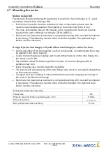
Design WR: maximum permissible number for installing several fan units on top of one
another
Size
External dimensions [mm]
Permissible number
1
607 x 607
5
2
760 x 760
5
3
912 x 912
5
Assembly instructions
ECblue
Mounting
L-BAL-F056-GB 2022/45 Index 005
Part.-No. 00700562-GB
16/44


