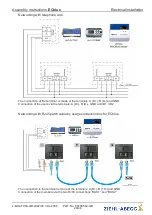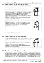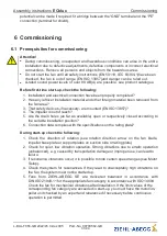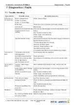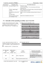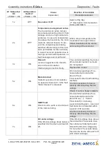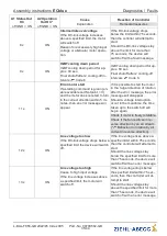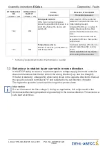
Information
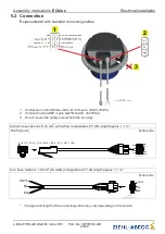
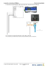
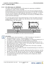
The respective connections are represented in the enclosure of this assembly
instructions (see Connection diagram)!
Connection to the terminals is only permissible with compatible counterparts!
5.3 Accessories: connection box
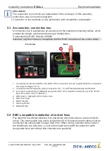
A connection box is available as an accessory for the standard connecting cables, which
enables the simple, quick and safe wiring of multiple fans.
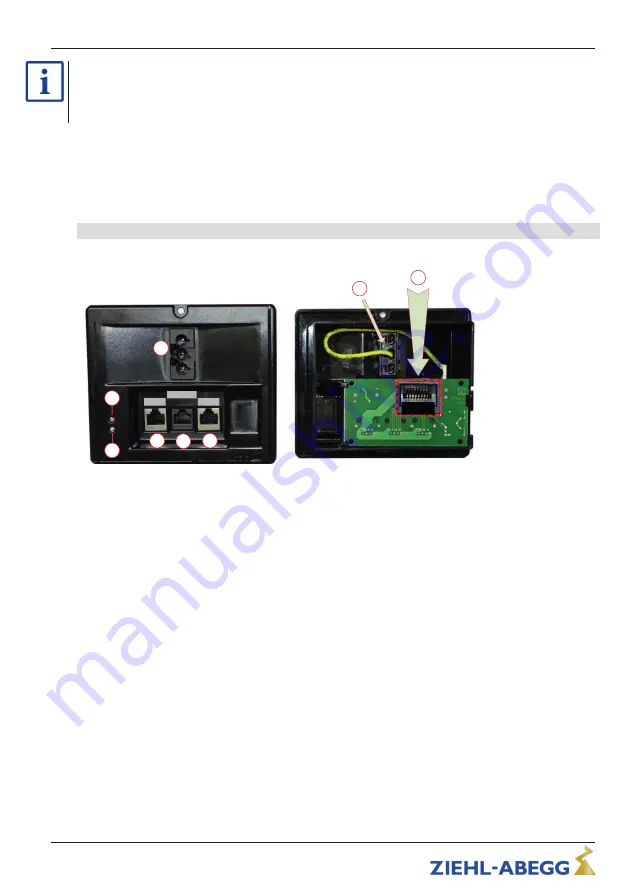
Connection box RJ45, Part-No. 380085
Attention: only this version is compatible with the RJ45 connection of the control cable!
Front view
Back
26.07.2013
v_ecblue_terminalbox_380085.vsd
3
4
5
6
7
8
BUS2
BUS1
Service
RJ45
2
1
1
Connection control fan (RJ45). The LEDs of the connection box are supplied from the connected
fan (output v10 V).
2
Connection line fan (tension clamp connection 0.5 - 1.5 mm
2
fl
exible with wire end ferrule)
3
Line input connection box (Wieland plug series GST 18i3, suitable socket part e.g. GST 18i3 S
B1 Z R1 or GST 18i3 1 F B2 Z R1)
4
LED green = Operation / Error
fl
ash code
5
LED red = fault
6
BUS1 (RJ45)
7
Service (RJ45)
8
BUS2 (RJ45)
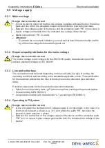
5.4 EMC-compatible installation of control lines
Pay attention to su
ffi
cient distance from powerlines and motor wires to prevent interfer-
ences. The control cable may not be longer than 30 m. Screened control cables must be
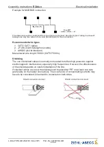
used when the cable length is longer than 20 m. When using a shielded cable connect
the shielding to one side only, i.e. only to the signal source with the protective earth
(keep cable short and with as little inductance as possible!).
Assembly instructions
ECblue
Electrical installation
L-BAL-F056-GB 2022/45 Index 005
Part.-No. 00700562-GB
21/44


