Zhejiang Qianjiang Motorcycle RKV 200 Service Manual Download Page 162


162 


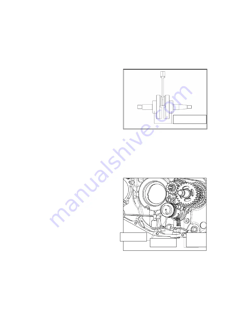
Check if the crank shaft is noisy or loose while restoring. 

Replace it if so. 


Note: both the crank connecting rod and the gearshift mechanism are installed on the crank case. 

Draw out the shifting fork. 

Remove the gearshift drum. 

Remove the gearshift fork. 


Crank shaft bearing 

Gearshift drum 

Gearshift 

fork 

Shifting fork 

Summary of Contents for RKV 200

Page 1: ...1 RKV 200 Motorcycle Service Manual...

Page 2: ...Fault diagnosis 72 2 3 Ignition system inspection 73 2 4 CDI Assembly 74 2 5 Ignition coil 75 2 6 Trigger 76 Starting System 78 3 1 Service Data 78 3 2 Fault Diagnosis 79 3 3 Starter Motor 79 3 4 Star...

Page 3: ...3 Fuel Tank Seat Cushion Engine Inspection and Maintenance Lubricating System 10 1 Service Data 10 2 Fault Diagnosis 10 3 Engine Oil Pump Carburetor 11 1 Service Data 11 2 Fault Diagnosis 11 3 Remova...

Page 4: ...haust System Inspection and Maintenance Emission Control System 15 1 Emission Control System Guarantee 15 2 Periodical Maintenance Instructions 15 3 Mechanical Functions of Emission Control System 15...

Page 5: ...e This shall be implemented from the time of periodical inspection The parts after Part 1 demonstrate breakdown assembly and main points of inspection of electrics finished motorcycle engine and other...

Page 6: ...ictly forbidden in working sites or gasoline storage places Battery Battery shall be away from spark open fire and smoking places since it may emit explosive gases Keep it in well ventilated condition...

Page 7: ...uring friction please clean the components and purge with air compressor Plastic parts may deteriorate due to aging which are apt to be damaged by solvent or oil Check before re installation and repla...

Page 8: ...to be damaged when installed Installation of rubber hose fuel vacuum or coolant insert its end into bottom of connector so that there is enough room for the hose clamp to grip the connector Install t...

Page 9: ...oving Prevent the cable from being pulled too tightly or slacking too much when the cable is wired along the handlebar pipe The cable shall not be affected by any adjacent components at any turning pl...

Page 10: ...tant Notes 1 Please use spare parts manufactured by Zhejiang Qianjiang Motorcycle Co Ltd Components that cannot comply with designed specifications of Zhejiang Qianjiang Motorcycle Co Ltd may result i...

Page 11: ...are required for smooth assembly and disassembly of some components on the engine Special tools and product pictures for engine component assembly and disassembly are listed in Table1 1 and Table 1 2...

Page 12: ...12 Figure 1 3 Figure 1 4 Figure 1 5 Figure 1 6 Figure 1 7 Figure 1 8 Figure 1 9 Figure 1 10 Handle...

Page 13: ...13 Figure 1 11 Figure 1 12 Pliers Piston Figure 1 13 Figure 1 14 Figure 1 15 Figure 1 16 Figure 1 17 Figure 1 18...

Page 14: ...Table1 25 Name Remarks Torque wrench Allen wrench Socket wrench Micrometer Magnetic stand V block Dial gauge Venier caliper Spring criclip pliers Hammer screwdriver Front fork oil seal installer Fron...

Page 15: ...15 Figure 1 27 Figure 1 28 Figure 1 29 Figure 1 30 Figure 1 31 Figure 1 32 Figure 1 33 Figure 1 34 Figure 1 35 Figure 1 36 2 Special tools for chassis overhaul front fork seal driver...

Page 16: ...Tools for electrical components Special tools and their pictures for electrical component test are listed in Table1 39 and Table 1 40 Table 1 39 Name Remarks Multimeter Ignition tester Figure1 41 Figu...

Page 17: ...n Tire Front tire 100 80 17 Air cleaner Paper element Rear tire 130 70 17 Drive Train Clutch type Wet multi plate friction type Fuel tank capacity 17 0 5L Gearshift pattern Five speed gearshift Perfor...

Page 18: ...18...

Page 19: ...o flywheel or trigger coil for looseness Loosen drain screw of carburetor and check if overflow pipe is clogged Refuel gasoline Check compression pressure in the cylinder with a pressure gauge Check o...

Page 20: ...Engine can continue to run when it is started Carburetor is clogged inside or float is too high Carburetor starter i e cranking enrichment system fails 1 Check leakage at external connection parts of...

Page 21: ...k if cooling fan or wind scooper is damaged forced air cooled engine Basically temperature of radiator and engine is consistent Temperature of radiator is lower than that of engine Oil cooling system...

Page 22: ...s explosion in the carburetor and power of the engine is insufficient Combustible gas mixture concentration is too high 1 Check if air cleaner is clogged 2 Check if Carburetor starter i e cranking enr...

Page 23: ...5 Check if conical surface of driven wheel and mobile driven wheel are excessively worn or worn to groove 6 Check if raceway on the inner end face of friction wheel is excessively worn or pitted due...

Page 24: ...just carburetor idle speed Check if jet of idle is too big Check if throttle control cable can pull flexibly in the cable jacket and if throttle spring is too soft 1 Check CDI ignitor 2 Check if magne...

Page 25: ...tire pressure Air pressure too low Air pressure normal Gas up as specified Check if fuel tank fuel switch delivery pipe or carburetor leaks oil Exclude as practice Check mixture ratio of combustible g...

Page 26: ...or replace Check if contact area between braking shoe and friction disc is worn terribly Repair or replace clutch shoe Refill engine oil Check if viscosity of engine oil in the crankcase is too low o...

Page 27: ...crankcase bleed surplus oil and decline oil level to upper limit line 1 Check if cylinder piston or piston ring is over worn 2 Check if elasticity of piston ring is not enough or stuck in the ring gr...

Page 28: ...is properly adjusted Re adjust Check if elasticity of clutch spring is even Replace the whole set of clutch spring Check if splines on clutch active and drive hubs are worn into zigzag form Repair or...

Page 29: ...Check if clearance of clutch handle bar is within 10mm 20mm 2 Check if elasticity of clutch spring is even 3 Check if splines on clutch active and drive hubs are worn into zigzag form 4 Check if clutc...

Page 30: ...hing end of cam pawl on end face of meshing gear is worn or forms great roundness and if corresponding gear end groove is worn or like a horn mouth Check if shift fork is overworn Replace gears Check...

Page 31: ...tuck by foreign substances 1 Check if there is oil adhered to the surface of brake shoe friction disc 2 Check if contact area between braking shoe and friction disc is less than 70 Hydraulic disc brak...

Page 32: ...ot be charged Resistance is less than standard Charging coil is shorted Resistance is infinitely great Resistance meets the standard Charging coil or its output wires are shorted Disconnect connectors...

Page 33: ...negative wire to check current leakage Leaking current is smaller than specified Leaking current is bigger than specified usually It shall be no more than 1mA Check if charging coil of magneto is sho...

Page 34: ...ush starter button and the click from starter relay cannot be heard Push starter button and a click from starter relay can be heard Disassemble the connector of starter relay from cables of the whole...

Page 35: ...heck if armature coil is broken or shorted 1 Check if contact inside clutch switch is poorly contacted 2 Check if starter button contact is poorly contacted 3 Check if rectifier diode is damaged 4 Che...

Page 36: ...check it for breakover Check if starter button contact is poorly contacted Disassemble starter motor and make the following inspections 1 Check if the carbon brush is over worn 2 Check if carbon brush...

Page 37: ...t engine and separate connectors of rectification regulator from cables of the whole vehicle Lights are lit Lights are not lit Short circuit inside rectifier Disassemble headlamp assembly and check if...

Page 38: ...e of wire to short circuit power line and output line of lighting switch Wiring from magneto or ignition switch to lighting switch is broken or shorted Lamp is lit after short circuit Lamp is still no...

Page 39: ...nsity of electrolyte in the battery is too low check if the base plate inside the battery is vulcanized or broken Separate conductors of rectification regulator from cables of the whole vehicle Measur...

Page 40: ...ables of the whole vehicle Check brightness of headlamp Headlamp light recovers after separation Headlamp light is still dim after separation Stable voltage of rectification regulator is too low Check...

Page 41: ...power of bulb in the lighting system is up to the requirement Replace the bulb 1 Check if headlamp switch and contact in the switch is poorly contacted 2 Check if connectors and earthing wire are poor...

Page 42: ...d the ground with a voltmeter No voltage displays No voltage displays Grounding wire of lamp holder is of poor contact or bulb of turn signal lamp is badly contacted with lamp holder Power line to the...

Page 43: ...ntact of turn signal lamp is poorly contacted Check if there is power output from power input line of turn signal lamp switch by lamp test Test lamp is on Test lamp is off power line of turn signal la...

Page 44: ...44 Symptom Electric horn mutes Diagnosis procedures...

Page 45: ...ound wire to check spark Spark at touch No spark at touch Connect well the power line of horn use a screwdriver to connect non power terminal terminal to button of horn with ground wire Power line bet...

Page 46: ...mp is not lit after short circuit Brake lamp is lit after short circuit Use a screwdriver or a piece of wire to touch quickly power line of brake lamp switch and grounding wire and check sparks Brake...

Page 47: ...sion system Carburetor Bolt nut fasteners Ignition timing Tire specification Wheel rim tire Basic Data General Precautions Warning Before running the engine please make sure if the workplace in is wel...

Page 48: ...Ignition time angle of before top dead center 1500RPM 15 CA 4000RPM 35 CA Frame Clearance of front brake handle 10 20mm Clearance of rear brake pedal 20 30mm Pneumatic pressure unit of tire Kpa Speci...

Page 49: ...tuating inspection I I I Common tool Inspection of looseness of bolts at all positions I I I I I I Torque wrench Check if gearbox leaks oil I I I I I I Common tool Spark plug inspection and replacemen...

Page 50: ...tenance shall be performed according to specifications on the user s manual unauthorized repair and adjustment are forbidden We will not be responsible for the results 2 You shall clean more frequentl...

Page 51: ...it Adjust clearance of throttle cable Procedures Loosen locknut Rotate adjusting nut inward or outward till it achieves specified clearance Rotate inward to increase clearance rotate outward to reduce...

Page 52: ...Inspection If the insulator is cracked or damaged If electrodes are worn Combustion condition and color Light grey color means excellent combustion condition Pale color indicates that ignition system...

Page 53: ...d damage battery It is dangerous Install the battery in reverse order of removal Warning To avoid short circuit please connect positive lead wire first and then the negative lead wire Battery charging...

Page 54: ...30minutes and then measure the battery voltage Charging current Standard 0 3A Quick charging 3 0A Charging time Standard 10 15hours Quick charging 30minutes After completion of charging open circuit...

Page 55: ...oes not rise Causes for low pressure Valve improperly adjusted Valve leaks air Worn piston ring or cylinder Causes for high pressure Carbon deposition in combustion chamber or on piston Stop engine an...

Page 56: ...e that filter screen spring O ring drain plug 1 and sealing ring 2 are perfect and then put them back onto the engine Attention Oil should be changed when the engine is warm Place the engine on the si...

Page 57: ...chain or sprocket will be worn soon Clearance of front rear brake Front brake clearance Measure clearance of front brake at the tip of front brake handle Clearance 10 20mm Brake pedal clearance Measu...

Page 58: ...or for the headlamp Screw tightly the new bulbs into the lamp holder Avoid touching bulb glass with your bare hands during installation and avoid staining them with oil which may affect transparency s...

Page 59: ...re loosened Rear Suspension Compress upward and downward the rear shock absorber to check its actuation Check if components on the rear shock absorber are loosened or injured Lift and support the rear...

Page 60: ...ft is loosened Check if locknut of rear shaft is loosened If loosened tighten it to specified torque Tightening torque Rear wheel lock nut 85 98 N m Steering stem bearing and handlebar fixation Move l...

Page 61: ...fasteners used in electric system Fastening positions and names of fasteners Tightening torque N m Starter motor clutch cover bolt Starter motor clutch locknut Rectifier bolt High voltage coil pinch b...

Page 62: ...62 Charging system Charging System 1 Variable frequency scintillator 2 Ignitor 3 Battery 4 Voltage regulator 5 High voltage ignition coil 6 Electric horn 7 Rectifier...

Page 63: ...the battery voltage or very low voltage on the terminals of the battery cannot be inspected If the regulator fails it will have too high voltage on the battery and the life span of the battery will be...

Page 64: ...Type Full wave rectification Battery charging voltage 14 5V 0 4V 5 000rpm Tightening torque Tools Rectifier bolt 5 0 N m Universal non adjustable spanner High voltage coil pinch bolt 9 0 N m Flywheel...

Page 65: ...wire Battery charging circuit voltage inspection Open the battery cover and remove battery pressure plate assembly Disconnect lead wire of the battery connector Measure voltage between terminals of th...

Page 66: ...d to negative lead wire of battery If abnormality is found check if there is short circuit on ignition switch and main wiring 1 4 2 Charging State Inspection While in inspection if the battery is full...

Page 67: ...terminals of voltage current regulator itself Attention Do not touch the metal part of multimeter probe with your finger Check with a multimeter If impedance values measured by different multimeters a...

Page 68: ...eel Remove the fixation key Disconnect lead wire connector of magneto Disconnect magneto stator 1 7 2 Installation Install the magneto stator onto the engine case Connect connector of magneto lead wir...

Page 69: ...agnetism on the inner surface of flywheel and make sure there is no bolt Fix the flywheel using a universal non adjustable spanner and then tighten the locknut Torque value 9 0 N m Install protecting...

Page 70: ...70 Ignition System 1 Variable frequency scintillator 2 Ignitor 3 Battery 4 Voltage regulator 5 High voltage ignition coil 6 Electric horn 7 Rectifier Ignition System...

Page 71: ...stem CDI shall not be dropped and hung or heavily knocked this is also the main reason for its failure Pay special attention to this while removing it 5 Most of the ignition system problems are due to...

Page 72: ...Ignition coil is no good Charging coil is bad Peak voltage measurement Secondary side voltage While no high voltage power supply high voltage power is sporadic Tester is wrongly connected Poor igniti...

Page 73: ...and make sure all the voltage values are normal There are many brands of multimeters with different interior impedance The values they measured are not the same Connect a high voltage shunt or an amm...

Page 74: ...to blue white negative to green white Min voltage higher than 1 7V Attention Please do not touch the metal parts of testing probe with your fingers while measuring voltage or you will be shocked Pleas...

Page 75: ...h is OFF Trigger Blue White White Green 100 200 Primary coil of ignition coil Black White Black 0 4 10 Secondary coil of ignition coil Black spark plug cap excluding spark plug 3 5 5K 10 2 5 Ignition...

Page 76: ...d Impedance value indicates broken wire inside the coil Remove the spark plug cap and measure impedance value between primary side lead wire of ignition coil cap and negative terminal Standard value 3...

Page 77: ...77 Starting System 1 Variable frequency scintillator 2 Ignitor 3 Battery 4 Voltage regulator 5 High voltage ignition coil 6 Electric horn 7 Rectifier Starting Schematic Diagram...

Page 78: ...on the engine Starter clutch removal refers to removal instruction Basic data Item Standard Service Limit Length of starter motor electric carbon brush 12 5mm 8 5mm Starter idler shaft bushing 8 3mm...

Page 79: ...tor the ignition switch must be set at OFF position Disconnect battery grounding wire and then turn on the power supply to check if the starter motor runs to confirm safety First remove the lead wire...

Page 80: ...nstall brush onto the carbon brush holder Apply lubricating grease on movable parts at both ends of brush shaft Press carbon brush into its holder and install front cover of electrodes Attention There...

Page 81: ...tage shall meet the specified When there is no voltage at wire terminal of starter relay inspect braking switch continuity and lead wire 3 4 3 Starter relay ground loop inspection Remove starter relay...

Page 82: ...e lamp 7 Rear right turn signal lamp A Headlamp certification No E4 0014699 B Front turn signal lamp certification No E4 50R 001732 C Tail lamp certification No E4 50R 0014700 D Rear turn signal lamp...

Page 83: ...ent 4 5 4 1 Service Data Precautions on operation Remove switches from the motorcycle and perform continuity test All the plastic connectors have pawls on them Release clamping of the pawl before remo...

Page 84: ...ake out of the lamp socket Attention When the bulb is lit keep you hands and inflammable materials some distance away from it Lighting bulb is hot touch it when it cools down 4 3 2 Installation Instal...

Page 85: ...order of removal 4 5 Tail lamp bulb replacement 4 5 1 Removal Screw off the two bolts Remove the tail lamp hood Disconnect wire connector to the tail lamp While pressing down the tail lamp rotate it c...

Page 86: ...order of removal 4 6 Instrument Remove rear mirror Take down the handle hood and pull out waterproof connector Remove the bolts Remove odometer assembly to take down the instrument Install the instru...

Page 87: ...4 9 Handle switch Remove protecting plate of steering handle Screw off mounting bolt on the brake lever and take down the bracket Remove bracket for the rear brake lever Remove throttle handle and bo...

Page 88: ...bolt Rear shaft locknut Steering handle welding assembly mounting bolt Front wheel shaft locknut Front shock absorber mounting bolt Rear wheel locknut Rear shock absorber top nut Rear shock absorber b...

Page 89: ...se mounting bolt 11 Brake hose assembly 12 Brake cylinder assembly 13 Friction lining assembly 14 Oil hose mounting bolt A Front brake disc diameter 260mm B Front brake disc thickness 4 0mm Service li...

Page 90: ...9 N m 1 Rear hydraulic brake assembly 2 Bushing 3 Yoke plate 4 Friction lining assembly 5 Brake cylinder assembly 6 Bolt M8 22 7 Sealing washer 8 Hex Flange head bolt 9 Brake hose assembly rear hydra...

Page 91: ...brake disc thickness 4 0 3 0 Front friction lining thickness 6 0 5 0 Rear hydraulic brake disc diameter 240 Rear hydraulic brake disc thickness 4 0 3 0 Rear friction lining thickness 6 0 5 0 5 1 2 Ti...

Page 92: ...tion Replace friction lining assembly If a friction lining assembly will be used again please mark it on the side before removal so as to re install it to its original place Steadily stand the motorcy...

Page 93: ...by grease or their thickness is smaller than service limit replace them Service limit Friction lining 5 0mm Hydraulic brake disc 3 0mm Note Friction linings shall be replaced in pairs 5 3 3 Installati...

Page 94: ...tion Replace braking shoes If a braking shoe will be used again please mark it on the side before removal so as to re install it onto its original place Remove the following assemblies from the rear w...

Page 95: ...Install rear brake cylinder assembly Install engine assembly and air cleaner assembly Install muffler assembly protecting plate assembly and seat cushion assembly Attention Tighten bolts and nuts to t...

Page 96: ...board right guard 11 Left guard 12 Trim board left guard 13 Left tail cap 14 Front part rear mud fender 15 Front part 1 rear mud fender 16 Rear mud fender 1 17 Rear mud fender 2 Attention Do not dama...

Page 97: ...quence Seat cushion assembly Left guard component Right guard component LR tail cap RR tail cap Left pedal Right pedal Reinforcing plate front mud fender Front mud fender Rear mud fender component Con...

Page 98: ...t wheel disk 7 Big gear drive vane 8 Oil seal component front wheel 9 Left bearing sleeve front wheel 10 Front braking disk 11 Mounting bolt hydraulic braking disk 12 Right lining front wheel 13 Sub a...

Page 99: ...fixing bolt 12 Bolt M6 25 13 Bolt M6 20 14 Fixed cover 15 Adjusting screw 16 Adjusting nut 17 Left handle base 18 Clutch wire sleeve 19 Socket head cap screw M6 35 20 Check valve flexible wire clamp 2...

Page 100: ...ad cap screw M6 30 18 Strut bolt 19 Lower interconnecting plate assembly 20 Combined screw M6 12 21 Hydraulic tube clamp 22 Hexagon socket set screws with flat point M4 6 23 Side reflective assembly 2...

Page 101: ...is important that any grease must not be attached on friction disc and its assembly as well as hydraulic braking disk Reference for motorcycle Measuring position Item Standard value mm Allowable limit...

Page 102: ...or gear housing is faulty 7 2 5 Abnormal noises from front shock absorber Noises due to friction against absorber guard Bolts of the absorber are loosened 7 3 Front wheel 7 3 1 Disassembly Attention...

Page 103: ...10 Remove the left bearing sleeve 9 of the front wheel to remove the oil seal 8 Remove the bearing 3 Check rotation of bearing If the bearing is found not to rotate or its rotation is found not to be...

Page 104: ...t will deform if the component is not aligned to the locked front wheel shaft The front hydraulic bake component is mounted onto the hydraulic braking disc Tighten the front wheel shaft Note See P75 o...

Page 105: ...Support the main stand of the motorcycle Remove the front wheel Remove the brake clamp and tube clamp Dismantle the front fender and the reflector Remove the handle pipe Loosen the clamping bolt upper...

Page 106: ...he number of steel balls 19 balls Apply grease onto the top housing washer Rotate the steering handle left and right so that steel balls are contacted and mated with each other closely Tool Fixing nut...

Page 107: ...disk 8 Bearing sleeve 9 Washer 16 32 2 10 Damper rear wheel 11 Left bearing sleeve component of rear wheel 12 Rear wheel shaft M14 1 5 292 13 Sub assembly of rear wheel 14 Vacuum tyre 15 Inflating val...

Page 108: ...108 Rear shock absorber 1 Domed nut M10 1 25 2 Mounting gasket rear shock absorber 3 Rear shock absorber component 4 Washer 12 Bolt M10 1 25 40...

Page 109: ...tive pad 6 Rear swingarm welding set 7 Chain regulator 8 Screw M5 12 9 Sleeve 2 10 Holddown plate chain regulator 11 Nut M8 12 Rear hydraulic brake cable clamp 13 Screw M6 12 14 Intermediate sleeve 15...

Page 110: ...Toothed sprocket sprocket 40 7 Anti loosening locking pad sprocket 8 Nut M10 1 25 9 Chain 428HG 1 124 10 Chain cover 11 Boss bolt 12 Dust shield sprocket hub 13 Sub assembly sprocket 11 Chain regulati...

Page 111: ...isc Reference Item Standard value mm Allowable limit mm Rear wheel wobbling Longitudinal direction 2 0 Horizontal direction 2 0 Locking torque force Fixing nut rear wheel 85 98 N m Top nut rear shock...

Page 112: ...talled incorrectly 8 2 5 Brake jarring Brake friction disc is worn Hydraulic braking disk is worn Brake friction disc is dirty Hydraulic barking disk is dirty 8 3 Rear wheel 8 3 1 Disassembly The moto...

Page 113: ...g 2 0mm Horizontal direction replacing in case of exceeding 2 0mm If the rear wheel wobbling exceeds the allowable limit the rear wheel bearing is loosened consequently the rear wheel wobbling Replace...

Page 114: ...and if it is fatigued replace the rear shock absorber component 8 4 Installation of rear shock absorber Installation must be initiated in the reverse sequence of dismantling Mount the upper fixing nut...

Page 115: ...equence of disassembly Apply grease onto the pivot bushing Check rear swingarm shaft sleeve component 2 and intermediate sleeve 3 Install chain guard Load the swingarm onto the frame and insert the re...

Page 116: ...gth of 10 links on different positions Clean the driving chain and place it into kerosene Clear dust as much as possible And then take the chain out of kerosene and dry it Check rotor and side panel I...

Page 117: ...replace it Check oil seal and replace it if it is damaged or worn 8 5 4 Installation Installation must be initiated in the reverse sequence of disassembly Install the driving chain chain cover LR shoc...

Page 118: ...ne tank turn the fuel switch to OFF B Torque force value of bolt 2 in the figure 22 29 N m C Torque force value of bolt 5 in the figure 22 29 N m 1 Cushion assembly 2 Bolt M8 20 3 RR rack rear carrier...

Page 119: ...nting pad 4 Fuel sensor component 5 Sensor rubber gasket 6 Nut M6 7 Tank switch component 8 Sealing gasket tank cover 9 Tank mounting pad 10 Tank mounting shaft sleeve 11 Rubber sleeve 12 Tank mountin...

Page 120: ...fuel switch to OFF During assembly tighten the bolt and nut to specified torque force value After assembly check if all parts are installed correctly and operated correctly Reference Item Standard All...

Page 121: ...engage the hook with frame and then remove the cushion 1 Remove the fuel level sensor cable connector Turn fuel switch to OFF OFF fuel hose Remove bolt gasket cushion and fuel tank Take tank from the...

Page 122: ...ouble end studs Flywheel locking bolt Valve clearance adjustment nut Gear shift locator bolt Closer bolt Right and left crankcase cover bolts Coil screw Oil filter cover bolt Clutch Fixing nut Cylinde...

Page 123: ...ncreasing tightness between cylinder ring and wall and cleaning and taking away foreign matters from surface of parts Precautions After engine oil pump is disassembled carefully clean its parts and pu...

Page 124: ...124 10 2Fault Diagnosis Gasoline volume decreases Engine damaged Gasoline is consumed naturally No or too low oil pressure Oil leakage Oil circuit clogged...

Page 125: ...nscrew the pump fixing screw after engine oil filter is removed and then remove the pump body driving gear and pump shaft Remove screws Remove the pump base Remove the pump cover and dismantle the pum...

Page 126: ...en inner and outer rotors Allowable limit 0 25mm Check clearance between outer rotor and pump base Allowable limit 0 25mm Check rotor face to face clearance Allowable limit 0 15mm Testing gauge Testin...

Page 127: ...ombined into the pump the inner and outer rotors must be free to rotate without jamming 10 3 2 Installation These parts are assembled in the reverse sequence of disassembly Diagram for lubricating sys...

Page 128: ...128 Swingarm Cam mechanism Piston Oil filter Engine oil pump Engine oil filtration net Cranksha ft...

Page 129: ...continuous and normal operation of engine Precautions The gasoline is combustible and explosive therefore operation must be conducted in a well ventilated place After the carburetor is disassembled t...

Page 130: ...rking badly Secondary air entering into intake system Too thick mixed gas Intermittent sparking during acceleration Enrichment valve working badly Too thin mixed gas Needle valve acting badly Too high...

Page 131: ...the component Check wearing of oil needle If any wearing is found replace it Loosen connecting screw of lower housing to remove the lower housing component and seal ring Remove the float component fl...

Page 132: ...t the engine speed is 1 500rpm Tighten the mixture adjusting screw completely and do not apply too big force Now the engine flames out if it does not flame out check if the air filter connection leaks...

Page 133: ...133 XII Cylinder head Valve Service Data 12 1 Fault Diagnosis 12 2 Cylinder Head 12 3 Inspection 12 4 Valve Guide Replacement 12 5 Valve Race Fixing and Adjustment 12 6...

Page 134: ...head 0 03 0 05 Valve Valve guide Valve clearance Intake 0 09 0 1 Discharge 0 09 0 1 OD valve rod Intake 4 965 4 975 4 9 Discharge 4 95 4 96 4 9 ID valve guide Intake 5 0 5 012 5 1 Discharge 5 0 5 012...

Page 135: ...3 1 Disassembly Loosen the two fixing bolts and remove the cylinder head cover swingarm and its shaft Release the tightener loosen the chain and unscrew cover nut to take down cam shaft bracket swing...

Page 136: ...m Clearance between swingarm hole and swingarm shaft Allowable limit 0 075mm Directly remove the cylinder head cover and compress the valve spring with the valve spring compression tool and remove the...

Page 137: ...the cover Allowable limit 0 05mm If the flatness exceeds the allowable limit place fine sands on a flat board engage the interfacing surface with the board and then grind in a 8 shape Measure free len...

Page 138: ...use a reamer to eliminate carbon accumulated within the guide Attention the reamer shall be turned clockwise and do not turn it counterclockwise Measure inner diameters of valve guides Allowable limi...

Page 139: ...g Heat the cylinder head to 100 150 with an electric oven or thermal oven Fix cylinder head and use the guide disassembly tool to remove the guide out of the head Place a new O ring onto the new guide...

Page 140: ...th of valve contact surface valve race width Allowable limit Intake discharge 1 3mm 12 6 Valve race fixing and adjustment Use a 45 cutter to clear coarse or uneven parts on the surface of valve race N...

Page 141: ...utter to clear 1 4 of bottom of race Remove the cutter and check the processed locations Use a 45 trimming cutter to grind the race so that it meets the suitable width Make sure all caves and unevenne...

Page 142: ...place the rod into the guide 12 8 Adjustment of valve clearance Check and adjust valve clearance when the engine has been in cooling status 1 Remove the eyelet cover engine cover and engine cover and...

Page 143: ...143...

Page 144: ...144...

Page 145: ...mber along with the cylinder cover Precautions All parts must be cleaned before being checked and purged with high pressure air Table for Standard Value and Allowable Limit of Reference Items Item Sta...

Page 146: ...e between crankcase and gas Too high compression pressure Abnormal noise from piston Too much accumulated carbon in Cylinder piston and piston ring worn or damaged combustion chamber Piston pin hole a...

Page 147: ...e piston ring Clear the accumulated carbon within the piston ring Install the piston ring Measure clearance between the piston ring and its slot Allowable limit Top ring 0 09mm Ring 2 0 09mm Remove th...

Page 148: ...t such position as to form 90 with piston pin and around 11mm from the piston skirt bottom Allowable limit 67 91mm Check of cylinder inner wall scratch and wearing Attention measure cylinder inner dia...

Page 149: ...Measure connecting rod small end ID Allowable limit 16 05mm 13 4 2 Installation of piston Install locating pin Apply engine oil on the piston rings and pistons and install the piston rings at their p...

Page 150: ...op is installed facing the intake valve 13 5 Installation of cylinder Install the gasket and locating pin on the crankcase Apply engine oil across the cylinder inner wall piston and piston ring Care s...

Page 151: ...rts must be cleaned before being checked and purged with high pressure air Prior to any operation release lubricating oil from the crankcase Table for Standard Value and Allowable Limit of Reference I...

Page 152: ...uiding pin broken Bad action of gearbox return spring Gear dog worn Gear shifting drum slot worn Automatic out of gear Joint dog worn and edge rounded Gear shift return spring force reduced Spline tee...

Page 153: ...uding sprocket and remove the idle gear of motor Remove the gasket Remove the gear display 14 3 2 Removal of right crankcase cover Loosen the fixing bolt and remove the right crankcase cover gasket an...

Page 154: ...ng for dismounted components Unscrew the lock nut with special tool to dismount the lock nut and thrust washer Dismount the center bearing bracket on the clutch Dismount the drive and driven friction...

Page 155: ...iction disc assembly 13 center bearing bracket 14 shaft sleeve 15 thrust washer 16 shell components Check Check if there are burrs or damage in the shell components of the clutch and get rid of them w...

Page 156: ...below 29 7 mm Measure the thickness of the friction disc with a vernier caliper Replace it if the limit is below 2 6mm Measure the flatness of the driven friction disc with a plug gauge Replace it if...

Page 157: ...he plane needle roller bearing Replace it if the limit is below 1 8mm Crank connecting rod combination and gearbox assembly Bolt Left crank case Locating pin Right crank case Crank connecting rod comb...

Page 158: ...158 Gearshift drum Shifting fork Shift rail Principal shaft assembly Vice shaft assembly...

Page 159: ...mechanism 1 gearshift mechanism 2 shaft sleeve 3 restoring spring 4 gearshift ratchet wheel 5 nut 6 upper baffle on the ratchet wheel 7 lower baffle on the ratchet wheel 8 pawl 9 jack prop on the paw...

Page 160: ...t with electric or compression tools Dismount the two wheels and the flat key Dismount the retainer ring remove the wheel gear on the fuel pump unscrew the nut in the fuel pump dismount the fuel pump...

Page 161: ...case 14 5 2 Check Measure the clearance on the left and right side of the big end of the collecting rod Allowable limit 0 05mm Measure the clearance along X Y direction of the big end of the connectin...

Page 162: ...ing Replace it if so Note both the crank connecting rod and the gearshift mechanism are installed on the crank case Draw out the shifting fork Remove the gearshift drum Remove the gearshift fork Crank...

Page 163: ...ole Allowable limit 10 05mm Measure the thickness of the shifting fork Allowable limit respectively 5 1mm and 5 35mm Measure the external diameter of the gearshift drum Allowable limit 39 75mm Measure...

Page 164: ...er 8 fourth gear wheel on the vice shaft 9 third gear wheel on the vice shaft 10 gearshift wheel 11 shaft sleeve 12 second gear wheel on the vice shaft 13 vice shaft 14 thrust washer 15 O seal ring 16...

Page 165: ...damages Note the removed bearing can not be used any more It should be replaced with a new one Special tool should be used to dismount the bearing and oil seal Remove the bearing in the right crank c...

Page 166: ...rication oil should be used on the wheel gears and shafts while assembling them Ensure the wheel gear works normally after the completion of the assembling work Note the assembling work of the crank c...

Page 167: ...the exhaust pipe 4 welded components on the muffler tail cover 5 combination screw M6 10 6 spring washer 8 7 protective shield on the exhaust pipe A Torsion force of the locating bolt 5 in the connect...

Page 168: ...d according to the intervals or distance of drive specified in our instructions b periodic maintenance adjustments or repair work is not done in our franchisers or service centers or no evidence of ma...

Page 169: ...maintenance table d no private adjustment or replacement can be done to the emissions control system including use of spark plug idling adjustment ignition timing and adjustment to the carburetor e N...

Page 170: ...and repair the engine Valve leakage Piston abrasion Combustion cleaning Qualified finished product Qualified Qualified Qualified Qualified Qualified 15 4 Solutions to the problem of idle exhaust excee...

Page 171: ...171 Complete QJ200 2A Schematic Circuit Diagram...

Reviews: