31
Wiring to the Channels
Wiring to the Channels
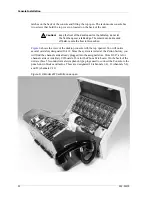
The radio channel interface is performed by the Dual Channel Cards. Each Dual Channel
Card has terminations for two transmit/receive channels, known as Channels A and B.
Each of the possible 12 channels in the system is referred to by a number; Channels 1-12.
The channel numbers that a Dual Channel Card is controlling depends only on the card-
slot into which the channel card is plugged. The odd number channel would be channel A.
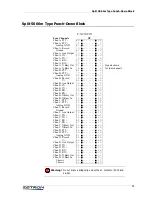
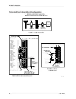
The connections between the Dual Channel Card and the radio base stations are made
through the three 50-conductor male chassis connectors (J2, J3 and J4) on the back of the
Console.
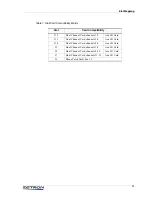
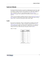
shows the channel allocations by slot designator and plug label.
Table 5: Radio Channel Connections
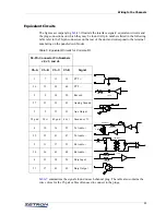
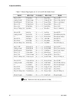
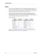
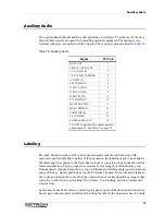
Since each 50-conductor plug carries signals for four radio channels, the channels on the
plug are referred to as channel A, channel B, channel C, and channel D. Each channel has
12 signals brought out on these plugs. These signals are the same regardless of the method
of control used by the Dual Channel Card.
The following subsections describe the channel signals.
Push to Talk +/-
The dry contacts across these two signals close whenever the channel is transmitting. This
may be used for single-function, local transmitter keying, or E&M signaling. The contacts
will handle 1 amp at 48 V. While the PTT contacts are closed, the XMIT indicator on the
channel card will be on.
Logging Recorder Output
Each channel provides a logging recorder analog audio output, which is the summation of
both the transmit and receive audio for the channel. The outputs are single-ended (not
balanced), AC-coupled, and provide about 0 dBm (0.75 V
rms
into 600
Ω
). The output does
not notch any guard tone frequencies that may be present; a third party notch filter can be
used. Analog ground is provided for the return path.
Card Slot
Channel Numbers
(A / B)
Plug
J12
1 / 2
J4 (A/B)
J11
3 / 4
J4 (C/D)
J10
5 / 6
J3 (A/B)
J9
7 / 8
J3 (C/D)
J8
9 / 10
J2 (A/B)
J7
11/ 12
J2 (C/D)

