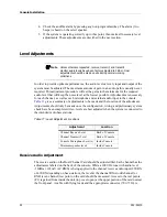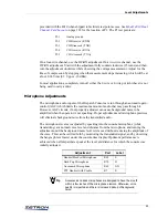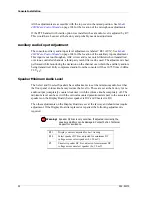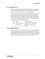
Console Installation
40
by lightly drawing a rectangle, .39" x .43" in dimension centered over the label words.
Insert the label into the clear key top with the bottom of the label orientated toward the
tabs of the key top. The key top is placed on the switch with the tabs down.
Model 4115B Connections
The expansion panel communicates with the dispatch console via a serial data loop. There
may be a maximum of three panels per position: one dispatch console, and optionally two
expansion panels. Each panel has a Loop In and a Loop Out connector. Every Loop Out
must be connected to the Loop In of the next panel with the supplied four-conductor
modular telephone-type cable. In this way, the data loops around from panel to panel in a
daisy chain.
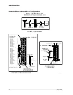
Power is supplied to the expansion panel via the loop cable from the Model 4010. Each
panel is also protected by a fuse labeled F2, which is accessible via the cutout in the rear
panel. It should be replaced only with a 2.0 ampere, AGC type fuse.
Loop Address
Because two expansion panels may be included in the data loop of the console, each of
these units must have a unique loop address to identify it from another identical unit.
Jumper JP1 on the back of the 4115B may be placed in position B or position C to
determine the panel loop address. No two units at the same console may have the same
loop address; otherwise, improper operation will result. The 60-button panel that is part of
the Model 4010 console is given address 1, so this address is not available for the
expansion panel. When one panel is added, it must be given address 2 (JP1 in position B).
The second expansion panel is given address 3 (JP1 in position C).
Loop Address Jumpers
JP1
A B C
JP1
A B C
First Expansion Panel
Second Expansion Panel
Address = 2
Address = 3

