51
Secondary Headset Jack Box
Installation
Installation requires mounting the SHJB, selecting interface operation via jumpers, wiring
the SHJB to the radio control console, wiring the jack box to other parallel jack boxes, and
optionally wiring the jack box to a footswitch.
Mounting
The SHJB can be mounted anywhere desired, but most frequently, it is installed under the
writing surface of the dispatch furniture. The top cover is removable so that it can be
secured to the bottom of the writing surface using the supplied screws. It is best to place it
at either end of the writing surface and far enough back so that the headset plug body is not
at risk due to chair movement.
Configuration
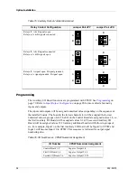
The SHJB circuit board is equipped with four user-configurable jumpers, which allow the
operation of the jack box to be tailored to the installation. The following jumper options
are available:
* = Factory jumper settings.
PTT override operation may be used if each secondary headset jack box is provided with
its own transmit switch (such as a foot-switch or 6-wire PTT headset). When PTT override
is enabled (JP1, JP3 and JP6 set to position B) pressing PTT on the primary jack box
mutes the secondary jack box transmit audio and routes the primary jack box audio to the
transmitter, allowing the primary jack box user to preempt (override) the secondary jack
box user.
If PTT override operation is desired only two jack boxes can be used on each console
position, one primary and one secondary.
Jumper
Operation
*JP1-A
Normal.
JP1-B
PTT Override (Must set JP3=B and JP6=B).
*JP3-A
Normal.
JP3-B
PTT Override (Must set JP1=B and JP6=B).
*JP5-A
For six-wire (w/ PTT) operation).
JP5-B
For four-wire (w/o PTT operation).
*JP6-A
Enables mouthpiece muting via local PTT.
JP6-B
Disables mouthpiece muting (mouthpiece always live).
This position should be set when used with a phone card.
Note
DO NOT install a four-wire plug into an SHJB configured for six-wire
operation. Doing so may cause the console to unexpectedly
transmit on the selected channel.

