19
Power
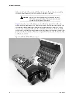
wiring may be necessary for ease of access. The rack-mount console requires the removal
of two screws that hold the top cover on. Access to the cards is then from the top of the
unit and probably requires the unit to be removed from the rack or furniture enclosure.
Power
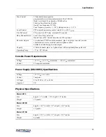
Primary Power
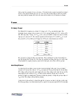
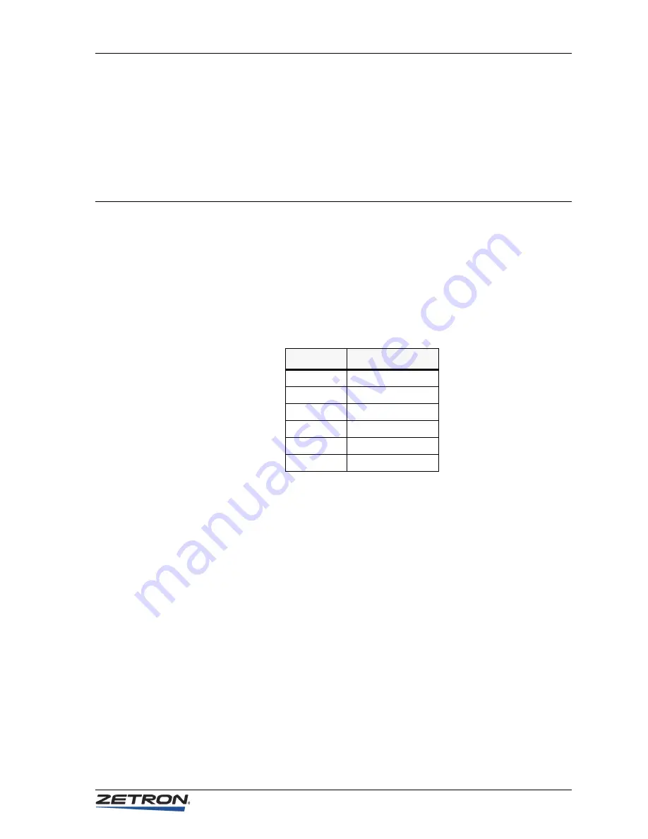
The Model 4010 requires an external 2.5 Ampere, 13.5 V
DC
regulated supply. The
minimum input voltage of the console is 11.5 V
DC
and maximum of 15 V
DC
. Zetron P/N
802-0092 provides 7 Amps, 13.5 V
DC
±
0.5 volts, with a DIN connector to mate with the
input power connector J5. The module operates with an input of 95 to 250 V
AC
, 47 to 63
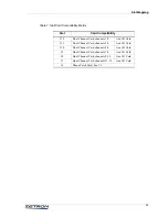
Hz, and is UL, CSA, VDE, and CE approved. The pin connections are as follows:
The console is equipped with an internal fuse. This is labeled F1 on the Control Board
near the input power connect J5. The fuse is accessible by lifting the top cover of the unit.
If replacement is required, replace only with 2.5-ampere, slow-blow AGC-type fuse.
Auxiliary Power
A connection for auxiliary power is also provided internal to the unit. Screw terminal
connector J16 is used to c12 V
DC
and ground. The specifications for the auxiliary
DC voltage is the same as the main supply, however the voltage level must not exceed the
main supply by more than 2.5 V
DC
or drain on the auxiliary supply may occur. The
auxiliary supply is automatically connected when the primary voltage drops more than 3.5
V
DC
below the voltage of the auxiliary supply.
Connection to the auxiliary is made through the wiring access hole in the back of the unit.
The three-position screw terminal strip J16 is used for connection and AWG #18 stranded
J5 PIN
SIGNAL
1
PWR-
2
Open
3
PWR+
4
PWR-
5
PWR+
Shell
Chassis GND