User’s Manual 1PH HYD3000-HYD6000-ZP1
Rev. 1.0 01/09/2023
Identification: MD-AL-GI-00
Rev. 1.1 of 27/01/2023 - Application: GID
38/193
5.3.
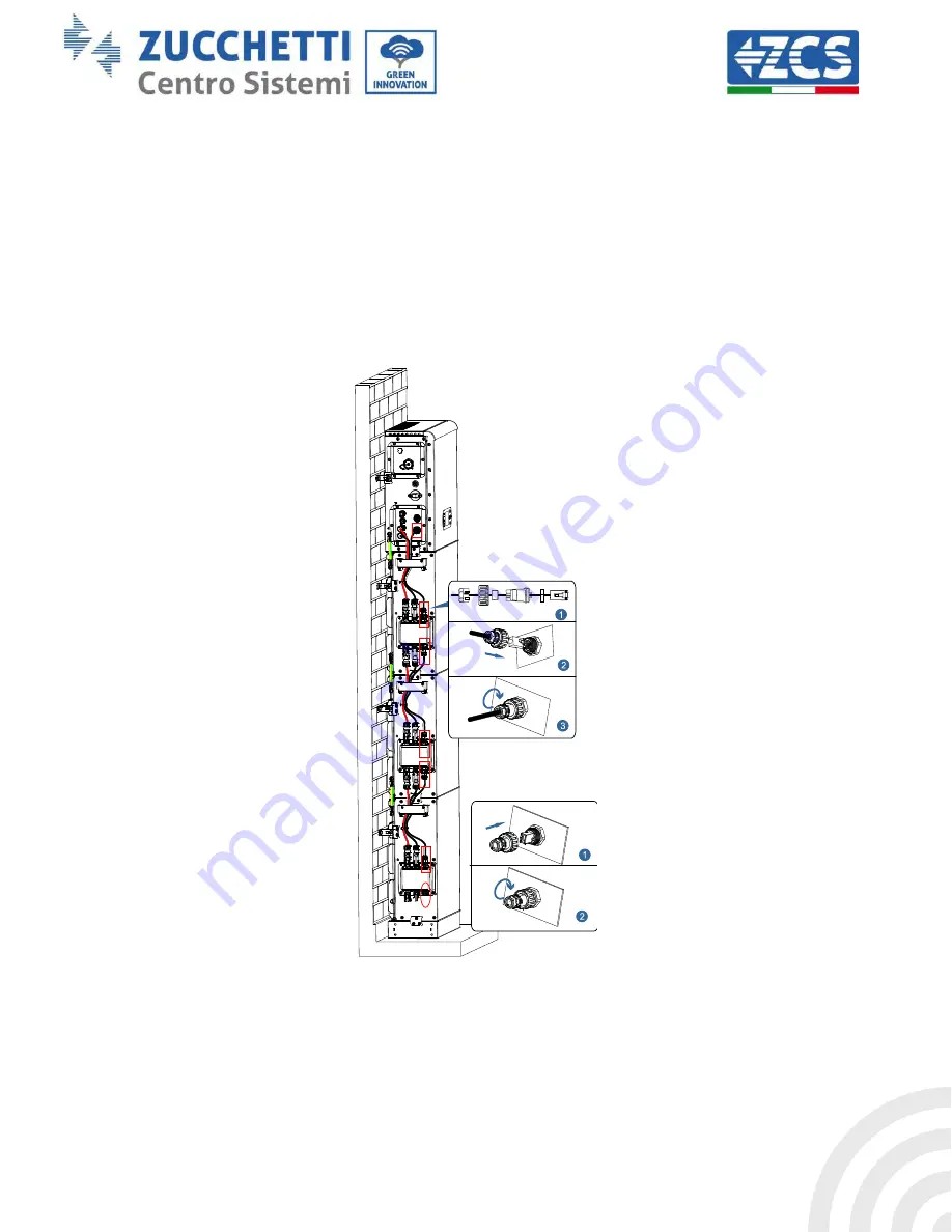
Internal communication cable connection up to 3 batteries
Connect the communication terminals of the inverter and battery module from top to bottom according to
internal protection grounding in the following figure, and secure them with cable ties. In addition, install a
matching resistor on the communication interface of the last battery module in the system.
In detail:
-
COM 1
of the Inverter
Link Port IN
of the
battery module 1
.
-
Link Port OUT
of the
battery module 1
Link Port IN
of the
battery module 2.
-
Link Port OUT
of
battery module 2
Link Port IN
of
battery module 3.
- Insert the termination resistor on
Link Port OUT
of the
battery module 3.
Figure 18 – Internal signal cable connection


