


114
YORK INTERNATIONAL
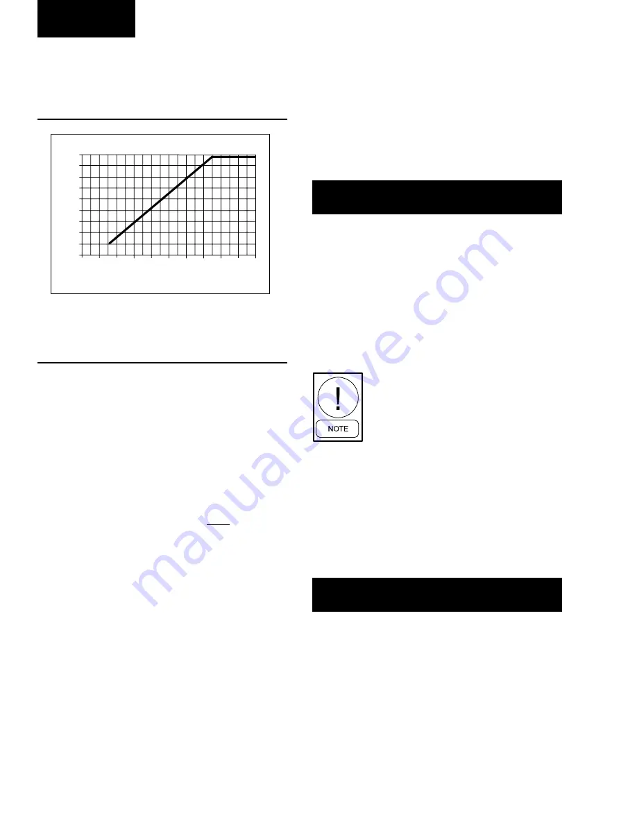
The following graph shows a typical programmed suc-
tion pressure cutout of 3 bar (44 PSIG) and its change
from time = 0 sec of compressor run time to 225 sec-
onds of compressor run time.
After 225 seconds of operation with suction pressure
operating above the cut-out, a 30 second transient timer
prevents short term fluctuations in suction pressure due
to loading or fan cycling from causing shutdown. If suc-
tion pressure drops below the cutout point after 225 sec-
onds of operation, the transient timer is activated. While
the transient timer is active, suction pressure must not
drop below 10% of the cut-out initially programmed and
must be greater than:
C.O. =
Programmed C.O. x
(
Time
+ 0.1 )
33.3
This transient cutout value increases with time until af-
ter 30 seconds it equals the programmed cutout value.
If the suction pressure falls below the value as calcu-
lated by the formula relative to time, the system will
shut down on a low suction pressure fault. If the suc-
tion pressure rises above the programmed cutout value,
the 30 second timer will be reset.
If the Dip Switch on the microprocessor board is set for
"Water Cooling" (see page 119), the cutout is program-
mable between 3 - 5 bar (44 - 70 PSIG) for both R-22
and R407c models. In this mode, settings of 3 bar (44
PSIG) for R22 and R407c are recommended. If the
Switch is set for "Brine Cooling" (glycol) the cutout is
programmable between 0.3 - 5 bar (5 - 70 PSIG) for R-
22 and R407c models. In this mode, the cutout should
typically be set to the saturated refrigerant pressure
equivalent to 10ºC (18ºF) below the temperature of the
chilled liquid. NOTE: The sludge point of the glycol
MUST be at least 11ºC (20ºF) below the equivalent cut-
out temperature. This programmable value is password
protected.
High Compressor Motor Current Cutout:
The High Motor Current Safety protects against exces-
sively high motor current and shuts a system down and
locks it out after only a single occurrence of a rise in
average motor current above the cutout point. Motor
current is monitored using 3 Current Transformers (CTs)
per motor, one on each phase.
Average motor current is monitored after 7 seconds of
compressor operation. The system will be shut down if
average motor current exceeds 115% FLA.
FLA (full load amps) is approximately
1.2 x RLA (rated load amps). RLA is
specified on the motor / chiller name-
plate and is typical current demand
under rated operating conditions in a
fully loaded system. When a system is
fully loaded, typical motor currents
may be at 60 - 85% FLA depending
on operating conditions.
Low Motor Current Cutout / Motor Protector (Hi
Motor Winding Temp Cutout) / Mechanical High
Pressure Cutout / External Motor Overload:
The Low Motor Current Safety prevents a compres-
sor motor running with less current than would normally
be expected. This may result from loss of refrigerant,
contactor, or power problems as well as from a com-
pressor that is not pumping due to a mechanical mal-
function. Motor current is monitored using 3 Current
Transformers (CTs) per motor, one on each phase.
Average motor current is monitored after 3 seconds of
compressor operation. From this time the system will
be shut down if average motor current is less than 10%
of FLA.
Suction Pressure Cutout With
44 PSIG Programmed Cutout
LD03525
0
30
60
90
120
150
180
210
240
270
310
45
40
35
30
25
20
15
10
5
0
Run Time (seconds)
Suction Pressure Cutout
FIG. 42 – SUCTION PRESSURE CUTOUT
S Y S
#
H I G H
M T R
C U R R
S Y S
#
H I G H
M T R
C U R R
S Y S
#
L O W
C U R R / M P / H P
S Y S
#
L O W
C U R R / M P / H P
Micropanel
Summary of Contents for MILLENNIUM YCAS
Page 53: ...53 YORK INTERNATIONAL FORM 201 18 NM2 WIRING DIAGRAM ACROSS THE LINE START 7...
Page 54: ...54 YORK INTERNATIONAL FIG 12 CONTINUED ELEMENTARY DIAGRAM Technical Data...
Page 59: ...59 YORK INTERNATIONAL FORM 201 18 NM2 WIRING DIAGRAM WYE DELTA START LD03229 FIG 15 CONT D 7...
Page 60: ...60 YORK INTERNATIONAL FIG 15 CONTINUED ELEMENTARY DIAGRAM Technical Data...
Page 62: ...62 YORK INTERNATIONAL FIG 16 POWER PANEL FRONT INSIDE VIEW WYE DELTA START Technical Data...
Page 68: ...68 YORK INTERNATIONAL FIG 24 DETAIL B Technical Data...


