6-2
<Toc>
<6. Function Block Diagram and Descriptions>
IM 05D01C12-41E
4th Edition: May 31, 2006-00
■
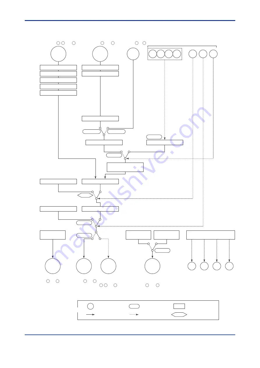
Function Block Diagram for Standard Type (UT450/UT420)
Communication
terminals to
Target setpoint selection
RMS=RSP
SPN
Target setpoints 1 to 8
REMOTE (ON)/LOCAL (OFF) switching
Communication
Aux.Input
R/L
RS485
Control computation
Manual operation
Alarm function
Preset output
AUTO (ON)/MAN (OFF) switching
STOP (ON)/RUN (OFF) switching
S/R
LOCAL
REMOTE
AUTO
MAN
RUN
STOP
A/M
Target setpoint
ramp-rate function
PV input
terminals , and
Remote input
terminals and
12
13
11
AL4
AL3
AL2
AL1
Alarm 1 Alarm 2 Alarm 3 Alarm 4
DI3
DI4
DI5
DI6
DI1
DI2
R/L
PV INPUT
RSP
INPUT
22
21
27
23
Input selection
Unit selection
Input range conversion
Input bias
Input filter
Input selection
Input range conversion
Remote setting filter
Ratio/bias calculation
Terminal
Parameter
Function
Analog signal
Contact signal
Front panel key
Legend
Contact input
OT
Control
output
OUTPUT1
OUTPUT1
17
16
Current or pulse
terminals and
Relay
terminals
, and
2
3
1
RET/LPS
15 V loop
power supply
Retransmission
output
Current
terminals
and
15
14
RET
Output limiter
RMS=COM
LPS
43
Terminals
and
44
24V loop
power supply
Summary of Contents for NEW GREEN SERIES
Page 2: ...Blank Page ...
Page 6: ...Blank Page ...
Page 56: ...Blank Page ...
Page 68: ...Blank Page ...
Page 86: ...Blank Page ...
Page 96: ...Blank Page ...
Page 97: ......


