5.6 Transferring the Waveform and Settings
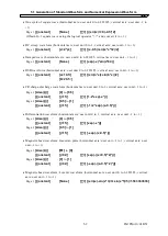
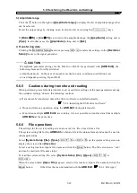
b) Interface selection
Click the button to the right of
[Interface]
to display the list of supported interfaces.
Click one in the list or press the
↑
↓
→
←
keys to select an interface.
The selected interface is saved even after the ARB Edit is exited and the same setting applies at the
next startup.
c) Serial number setting
Click the button to the right of
[Serial Number]
to display the list of connected signal detector
to serial numbers. Click one in the list or press the
↑
↓
→
←
keys to select a serial number.
If not a single unit is connected, “None” is displayed and no item other than “None” can be selected.
Check the signal generator to be connected for its serial number.
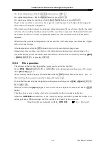
5.6.2 Axis unit setting
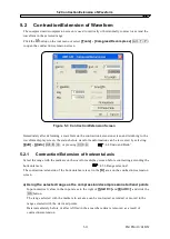
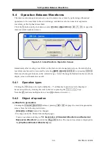
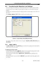
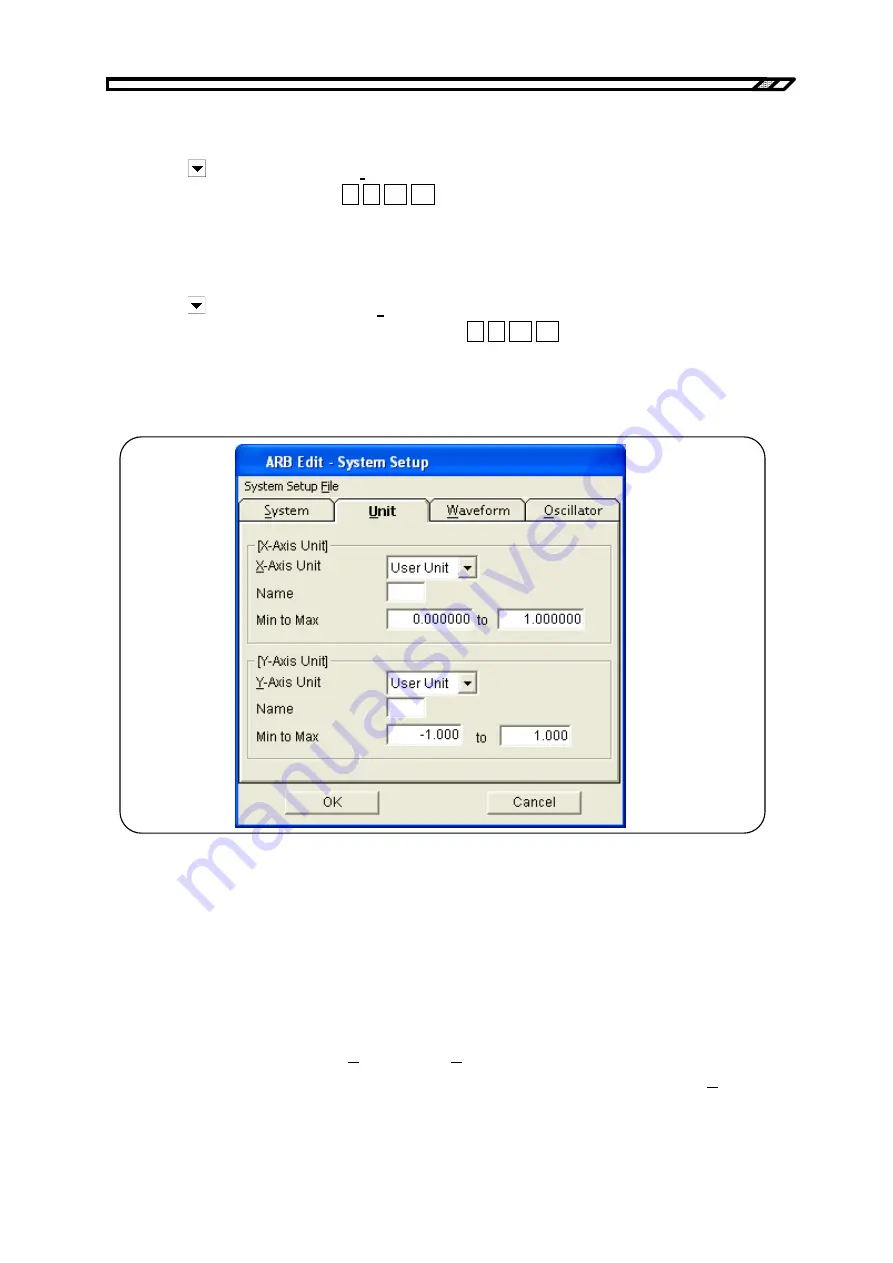
Figure 5-8 System Setup Screen
−
Unit Setup
In the
[X Axis Unit]
and
[Y Axis Unit]
fields on the
[Unit]
page, perform the settings of the
horizontal axis and vertical axis for waveform display.
On the system setting screen, double-click the
[Unit Setup]
to enable the
[Unit]
page.
a)
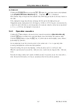
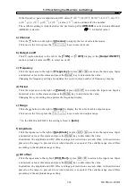
Horizontal axis unit
The time and the user unit can be used as the display/setting unit of the horizontal axis in addition to
the waveform data address.
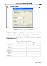
The time is interlocked with
[Frequency]
and
[Period]
in
[Oscillator]
.
From the head to the tail of waveform data, that is, one cycle corresponds to
[Period]
in
[Oscillator]
.
For example, this function is useful when creating a waveform through interpolation by setting the
IM FG410-61EN
5-23
Summary of Contents for FG410
Page 1: ...User s Manual FG410 FG420 ARBITRARY WAVEFORM EDITOR IM FG410 61EN 3rd Edition ...
Page 3: ......
Page 10: ...1 OVERVIEW 1 1 General 1 2 1 2 Function Tree 1 2 1 3 Conventions 1 5 ARB Edit 1 1 ...
Page 15: ...1 3 Conventions IM FG410 61EN 1 6 ...
Page 44: ...4 7 Copy and Paste IM FG410 61EN 4 15 ...
Page 45: ......
Page 76: ...6 ERROR MESSAGES 6 1 Arbitrary Wave Edit Software Error 6 2 IM FG410 61EN 6 1 ...
Page 80: ......
Page 82: ......
Page 83: ...https www yokogawa com ymi Yokogawa Test Measurement Corporation ...

