3.6 Waveform Generation Through Interpolation
3.6 Waveform Generation Through Interpolation
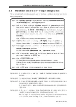
This section explains how to create a smooth pulse waveform, as a sample of generating a waveform
through interpolation.
Step 1: Select
[Setup] - [Setup]
to display the dialog box titled
[YOKOGAWA ARB Edit
- System Setup]
. Next, click the
[Unit]
page tab.
Step 2: Click the button to the right of
[X-Axis Unit]
and click
[User Unit]
from the
displayed list. Leave the minimum value to the maximum value two lines below as
their initial values,
[0.000000 - 1.000000]
. Click the button to the right of
[Y-Axis Unit]
and click
[User Unit]
from the displayed list. Leave the minimum
value to the maximum value two lines below as their initial values,
[-1.000000 -
1.000000]
.
Click the
OK
button to return to the waveform display screen.
Step 3: Set
[0.2]
in the number area to the right of
[MrkA(X)]
and press the
Enter
key.
Set
[0.8]
in the number area to the right of
[MrkB(X)]
and press the
Enter
key.
Step 4: Click the button at the top left of the screen. The same result can be obtained when
[Tools] - [Interpolate]
is selected.
The screen titled
[YOKOGAWA ARB Edit - Interpolate]
appears.
Step 5: Click the cell for the Y value next to X which shows
[0.5]
on the list of the control
points, input 1, and press the
Enter
key.
Step 6: Click the
Cont Spline
button.
The interpolated waveform is displayed on the waveform display screen.
If the waveform is hidden behind the interpolation editing screen and difficult to see,
move the screen.
Step 7: Click the
Exit
button to return to the waveform display screen.
Explanation 1: If the setting in step 1 and step 2 is already the default setting, no operation is
required.
Explanation 2: The point set at step 5 is called “
control point
” in interpolation editing.
Explanation 3: In the case of linear interpolation, the waveform is created by interpolating spaces
between control points with straight line.
In the case of a spline, spaces between control points are smoothly interpolated with
spline curve.
Explanation 4: In the case of a continuous spline, the selected range is interpolated so that it is
smoothly connected to the previous and subsequent ranges as well.
When all ranges are selected, the waveform is interpolated so that the head and tail
of the waveform can be smoothly connected if the waveform is repeated.
IM FG410-61EN
3-6
Summary of Contents for FG410
Page 1: ...User s Manual FG410 FG420 ARBITRARY WAVEFORM EDITOR IM FG410 61EN 3rd Edition ...
Page 3: ......
Page 10: ...1 OVERVIEW 1 1 General 1 2 1 2 Function Tree 1 2 1 3 Conventions 1 5 ARB Edit 1 1 ...
Page 15: ...1 3 Conventions IM FG410 61EN 1 6 ...
Page 44: ...4 7 Copy and Paste IM FG410 61EN 4 15 ...
Page 45: ......
Page 76: ...6 ERROR MESSAGES 6 1 Arbitrary Wave Edit Software Error 6 2 IM FG410 61EN 6 1 ...
Page 80: ......
Page 82: ......
Page 83: ...https www yokogawa com ymi Yokogawa Test Measurement Corporation ...


