5.3 Waveform Generation Through Interpolation
5.3.1 Control point setting
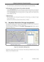
Interpolation is applied to the range selected by markers on the waveform display screen.
In the initial state, the following three control points are displayed.
[0.0, 0.0] [0.5, 0.0] [1.0, 0.0]
a) Specifying the control point with a numerical value
Click the index cell in the control point list on the interpolation editing screen and then click the
Insert
button to insert and display a new data line. At this time, value X is the intermediate
value of the previous and following values, and value Y is 0.0.
Click the X or Y cell and change their respective values. The value X that can be input must be
within the range defined by the previous and following control points. Also, X cannot be changed
if it is 0 or 1.
Value Y when X = 1 is the same as when X = 0.
Control points are displayed a
[+]
mark at the specified position in the waveform display area.
b) Specifying the control point with mouse
If any of control points’
[+]
marks are shown in red (selected), click an unmarked location of the
waveform display area to change all marks to light blue (deselected).
c) Moving the control point with mouse
The control point can be moved by dragging the
[+]
mark on the waveform display screen. If the
screen magnification ratio is low, it might be difficult to capture the mark due to the display
resolution.
When a control point is moved with the mouse, linear interpolation is performed and the
waveform display area is overwritten.
d) Deleting the control point
Click the
Delete
button to delete the selected control point.
The selected control point cannot be restored. Take care when using this function.
e) Deleting all the control points
Click the
Delete All
button to select all the set control points. All the set control points are
deleted and the three control points of the initial state are displayed.
The selected control points cannot be restored. Take extra care when using this function.
5.3.2 Interpolation
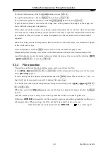
When the range is selected and the control points are set, perform interpolation. The following three
types of interpolation methods are possible.
•
Linear interpolation where the spaces between control points are interpolated with a straight line
•
Spline interpolation where the spaces between control points are interpolated with a smooth curve
•
Continuous spline interpolation to use such a curve that the waveform is continued outside to the
selected range for interpolation
IM FG410-61EN
5-14
Summary of Contents for FG410
Page 1: ...User s Manual FG410 FG420 ARBITRARY WAVEFORM EDITOR IM FG410 61EN 3rd Edition ...
Page 3: ......
Page 10: ...1 OVERVIEW 1 1 General 1 2 1 2 Function Tree 1 2 1 3 Conventions 1 5 ARB Edit 1 1 ...
Page 15: ...1 3 Conventions IM FG410 61EN 1 6 ...
Page 44: ...4 7 Copy and Paste IM FG410 61EN 4 15 ...
Page 45: ......
Page 76: ...6 ERROR MESSAGES 6 1 Arbitrary Wave Edit Software Error 6 2 IM FG410 61EN 6 1 ...
Page 80: ......
Page 82: ......
Page 83: ...https www yokogawa com ymi Yokogawa Test Measurement Corporation ...


