


<8. Setting Parameters>
8-11
IM 01C27B01-01EN
• When changing the device information, input
the information based on the following limitation
on the number of characters.
- Message function (up to 32 characters)
TRANSDUCER block: Tag Description
AI1-AI3 block: Tag Description
8.3.5 Unit
The unit parameter is set at the factory before
shipment if specified at the time of order. Follow the
procedure below to change the unit parameter.
• Procedure to call up the Unit display (Units
Index)
Al1 - Al3 block: SCALE: Units Index
To change the Unit display, choose desired unit
among the list of displayed unit selecting AI1
block as for the differential pressure/pressure,
AI2 as for the static pressure and AI3 block as
for temperature in the AI blocks.
8.3.6 Range Change
The range values are factory-set as specified by
the customer. To change the range, follow the steps
below.
The measurement span is determined by the upper
and lower range values. In this method, the upper
and lower range values can be set independently,
and the span changes according to the range limit
values sent to the transmitter.
• Procedure to call up the PV Range display.
AI1, Al2 block: PV Range
Select the AI1 block for the differential pressure/
pressure and the AI2 block for the static
pressure, then select “EU at 0%” and “EU at
100%” displayed in the PV Range parameters,
and input the lower range and upper range
values for the range, respectively.
8.3.7 Output Mode
The output mode of the output signal can be set as
No Linearization or Sq root.
• Procedure to call up the Linearization Type
display
AI1 block: Linearization Type
Select the AI1 block for the differential pressure
and then select No Linearization or Sq root for
the Linearization Type parameter.
8.3.8 Output Signal Low Cut Mode Setup
Low cut mode can be used to stabilize the output
signal near the zero point.
( There is 10% of hysteresis at only point of
transition from low to high)
[Setup Low Cut Value]
• Procedure to call up the Low Cutoff* display
AI1 block: Low Cutoff*
Example: setup LOW_CUT of output to 15%
*Low Cutoff
= (“Eu at 100%” - “Eu at 0%”) × 0.15 + “Eu at 0%”
[Setup Low Cut Mode]
• Procedure to call up the Low Cut Mode display
AI1 block: Low Cut Mode
Example: Low cut at 20%
(%)
50
20
0
50 (%)
For low cut in Linear mode
For low cut zero mode
[ sq root output ]
Example: Low cut 20%
Input
(%)
50
20
0
50 (%)
Example: Low cut 20%
F0804.ai
(%)
50
20
0
50 (%)
For low cut in Linear mode
[ Linear output ]
Example:
Low cut 20%
Output
Output
Input
Input
Output
Figure 8.2
Low Cut Mode
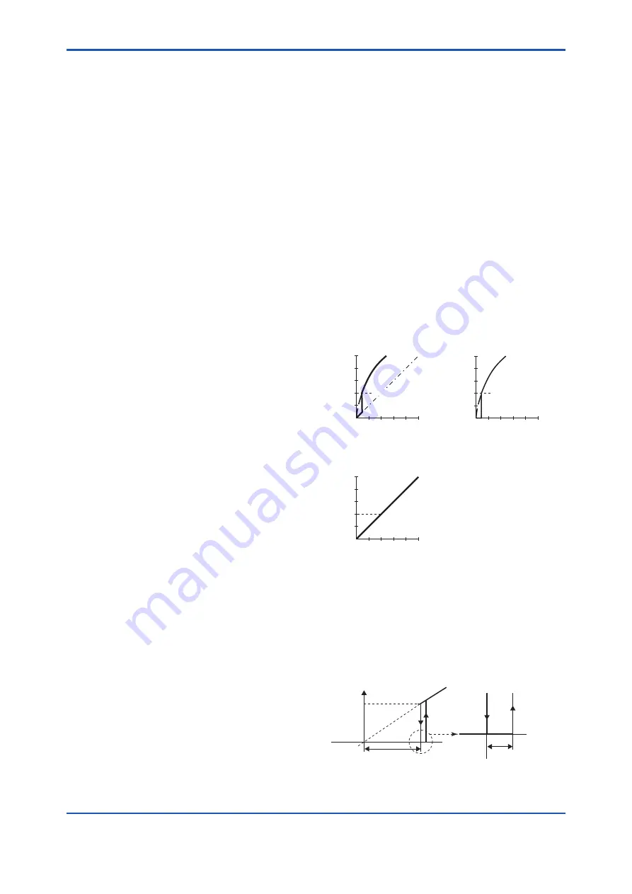
The low cut point has hysterisis so that the output
around the point is behaved as below figure.
<Example>
Output mode: Linear
Low cut mode: Zero
Low cut: 20.00%
Output
Setting range:
0 to 20%
Input
0%
(20%)
2%
Low cut
point
Hystrersis fixed at 10%
of the cut point
F0805.ai


