YG125-30B
Maintenance Manual
Fuel system
44
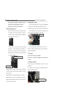
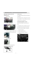
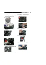
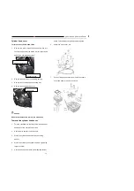
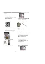
Remove and installation of throttle body
Disassemble step
:
1.
Removal of rear wheel
2.
Removal of seat
3.
Removal of fuel tank
4.
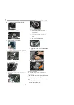
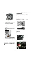
Loosen inlet pipe clip;
5.
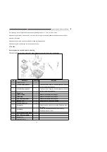
Remove throttle body (including the fuel
injector).
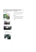
Installation steps
:
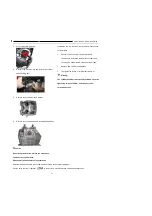
The installation procedures are the removal procedures in
reverse order. While installing, the locating slot must be
aligned with the locating lobe of throttle body
Warning:
Do not further disassemble the removed throttle body;
in case several sensors on it need to be changed,
proceed under the instruction of an EMS system
technician.
Summary of Contents for YG125-30B
Page 99: ...YG125 30B Maintenance Manual Frame and exhaust system 106 10 Frame and exhaust system...
Page 130: ...YG125 30B Maintenance Manual Illumination signal system 136 Circuit schematic drawing...
Page 141: ...YG125 30B Maintenance Manual Engine management system 147 Circuit schematic drawing...
Page 151: ...YG125 30B Maintenance Manual Electrical System Diagram 157 19 Electrical System Diagram...

