

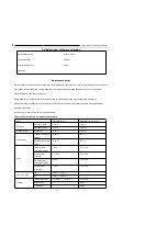


YG125-30B
Maintenance Manual
Cylinder Head, Cylinder and Piston
57
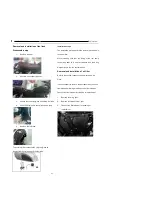
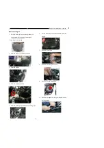
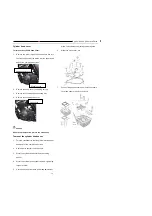
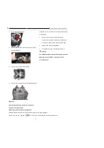
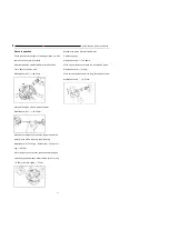
Camshaft
To remove the camshaft:
1.
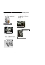
Remove the lower / upper eyehole cover and turn
the crankshaft so that the piston is at the upper dead
point of the compression stroke.
2.
Remove the cylinder head cover (See Removal of
cylinder head cover)
.
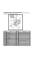
3.
Remove the camshaft end cover, loosen the screw
and washer at the tail end of the tensioner; turn the
screw clockwise with the tensioner locking key
so that the tensioner is loosened and locked.
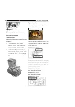
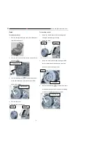
4.
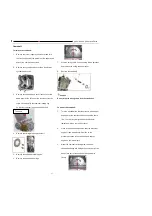
Remove the timing driven sprocket bolt
5.
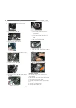
Remove the camshaft retaining pins
6.
Remove the camshaft bearings
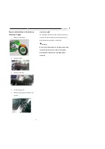
7.
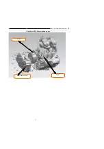
Strip the timing chain from the timing driven sprocket,
and remove the timing driven sprocket.
8.
Remove the camshaft
Caution
Do not drop the timing chain into the crankcase.
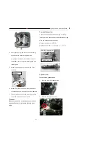
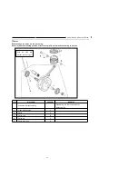
To mount the camshaft:
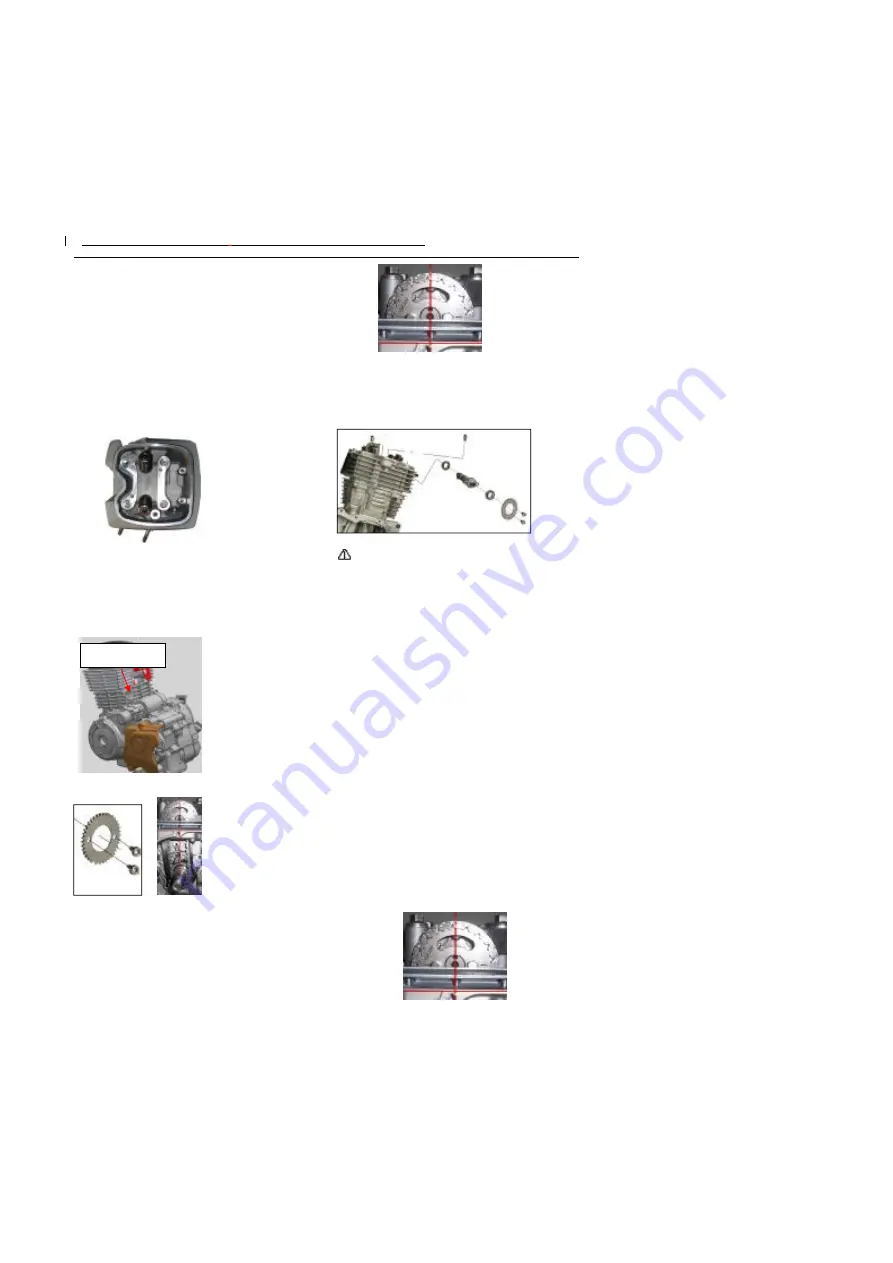
1.
Turn the crankshaft so that the piston is at the upper
dead point of the compression stroke and the scale
line
“
I
”
on the rotor is aligned with the triangular
indication mark on the left front cover.
2.
Clean all parts and components, coat the mixture of
engine oil and molybdenum disulfide on the
protruding surface of the camshaft, and coat oil
engine on the journal part.
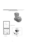
3.
Mount the camshaft retaining pins, camshaft
,
camshaft bearings and timing driven sprocket; let the
basic circle part of the camshaft facing up while
timing.
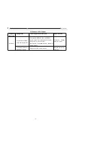
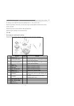
Tensioner
Summary of Contents for YG125-30B
Page 99: ...YG125 30B Maintenance Manual Frame and exhaust system 106 10 Frame and exhaust system...
Page 130: ...YG125 30B Maintenance Manual Illumination signal system 136 Circuit schematic drawing...
Page 141: ...YG125 30B Maintenance Manual Engine management system 147 Circuit schematic drawing...
Page 151: ...YG125 30B Maintenance Manual Electrical System Diagram 157 19 Electrical System Diagram...