YG125-30B
Maintenance Manual
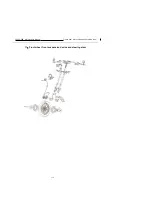
Front wheel, front suspension device and steering stem
115
Control subassembly
1
、
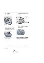
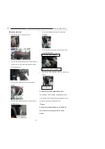
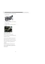
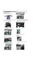
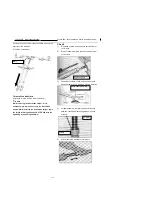
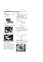
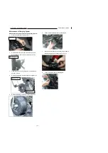
Remove the left/right balance weight.
2
、
Remove the right handle and right combination switch
l
Pull off the brake switch leads
l
Remove the upper/lower body of the right
combination switch
l
Remove the throttle control line
l
Remove the right combination switch
l
Remove the right brake cylinder body.
l
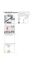
Remove the clutch control line and disassemble the
connection of the clutch switch leads and the main
cable.
l
Remove the left combination switch.
l
Loosen the retaining bolt and remove the clutch
handle holder.
Brake switch
Remove the upper/lower body
Throttle control line
Right combination switch
Remove the right brake cylinder body
Remove the left combination
Clutch control line
Retaining bolt
Remove the left
combination
Summary of Contents for YG125-30B
Page 99: ...YG125 30B Maintenance Manual Frame and exhaust system 106 10 Frame and exhaust system...
Page 130: ...YG125 30B Maintenance Manual Illumination signal system 136 Circuit schematic drawing...
Page 141: ...YG125 30B Maintenance Manual Engine management system 147 Circuit schematic drawing...
Page 151: ...YG125 30B Maintenance Manual Electrical System Diagram 157 19 Electrical System Diagram...

