8 Operation
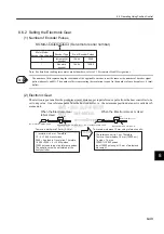
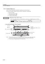
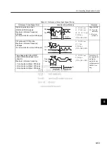
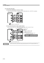
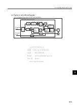
8.6.2 Setting the Electronic Gear
8-50
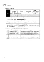
(3) Related Parameters
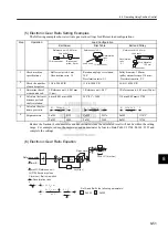
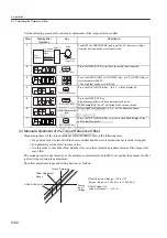
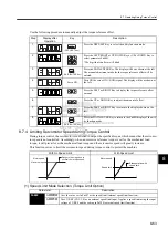
(4) Procedure for Setting the Electronic Gear Ratio
Use the following procedure to set the electronic gear ratio.
Pn202
Electronic Gear Ratio (Numerator)
Setting Range
Setting Unit
Factory Setting
Setting Validation
1 to 65535
−
4
After restart
Pn203
Electronic Gear Ratio (Denominator)
Setting Range
Setting Unit
Factory Setting
Setting Validation
1 to 65535
−
1
After restart
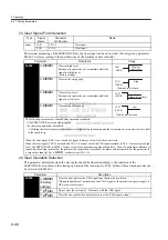
If the deceleration ratio of the servomotor and the load shaft is given as n/m where m is the rotation of the servomotor and
n is the rotation of the load shaft,
* If the ratio is outside the setting range, reduce the fraction (both numerator and denominator) until you obtain integers
within the range. Be careful not to change the electronic gear ratio (B/A).
IMPORTANT
Electronic gear ratio setting range: 0.01
≤
Electronic gear ratio (B/A)
≤
100
If the electronic gear ratio is outside this range, the SERVOPACK will not operate properly. In this case, modify the load
configuration or reference unit.
Position
Position
Electronic gear ratio:
=
A
B
Pn203
Pn202
=
n
m
No. of encoder pulses
×
4
Travel distance per load
shaft revolution (reference units)
×
Step
Operation
Description
1
Check machine specifications.
Check the deceleration ratio, ball screw pitch, and pulley diameter.
2
Check the number of encoder pulses.
Check the number of encoder pulses for the servomotor used.
3
Determine the reference unit used.
Determine the reference unit from the host controller, considering the
machine specifications and positioning accuracy.
4
Calculate the travel distance per load shaft
revolution.
Calculate the number of reference units necessary to turn the load
shaft one revolution based on the previously determined reference
units.
5
Calculate the electronic gear ratio.
Use the electronic gear ratio equation to calculate the ratio (B/A).
6
Set parameters.
Set parameters using the calculated values.
Summary of Contents for SGDJ Series
Page 19: ...xix INDEX Revision History ...
Page 34: ...2 Selections 2 8 2 4 Selecting Cables CN4 c d e FG ...
Page 176: ...8 3 8 ...


