8.4 Absolute Encoders
8-31
8
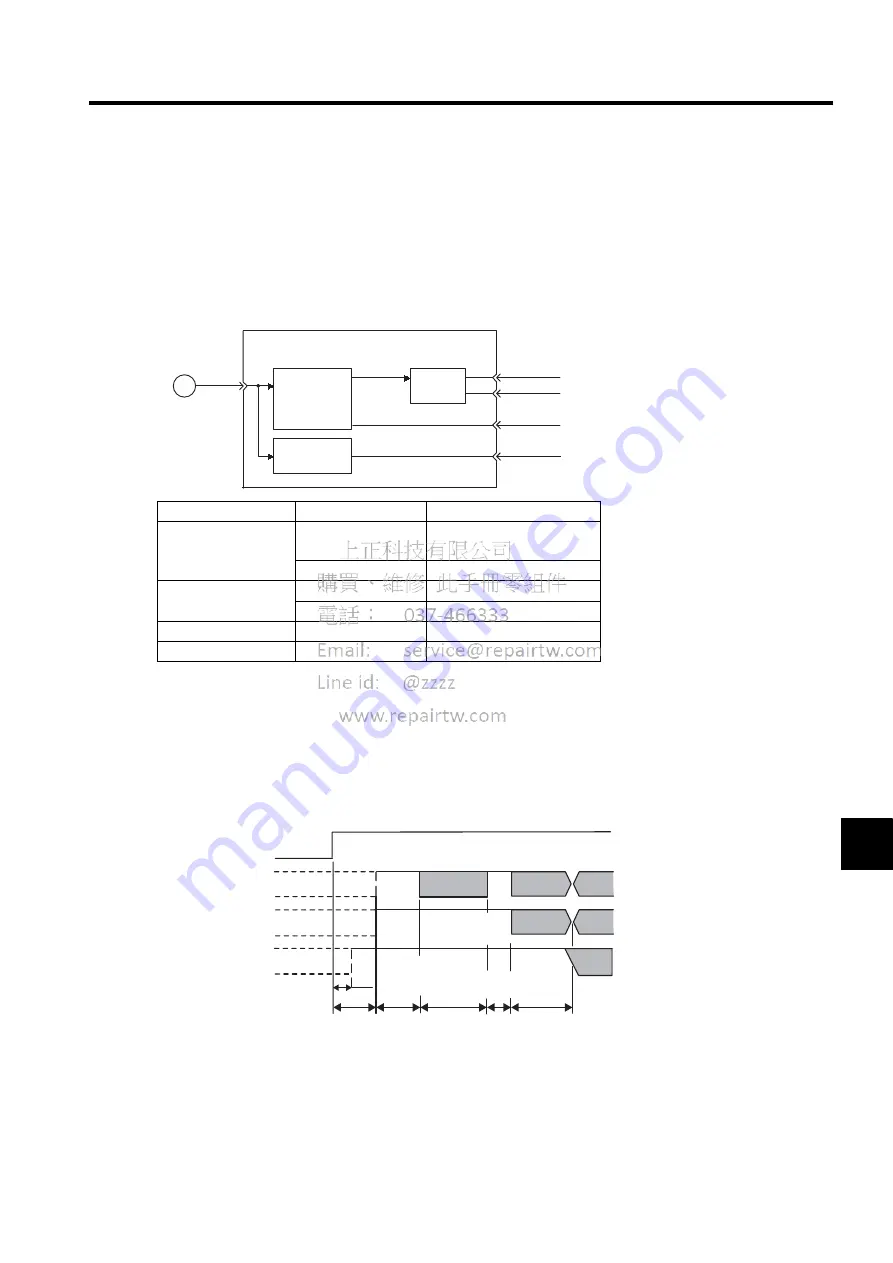
8.4.6 Absolute Encoder Reception Sequence
The sequence in which the SERVOPACK receives outputs from the absolute encoder and transmits them to host
controller is shown below.
(1) Outline of Absolute Signals
The serial data, pulses, etc., of the absolute encoder that are output from the SERVOPACK are output from the
PAO, PBO, and PCO signals as shown below.
(2) Absolute Encoder Transmission Sequence and Contents
1. Set the SEN signal at high level.
2. After 100 ms, set the system to serial data reception-waiting-state. Clear the incremental pulse up/down
counter to zero.
3. Receive eight bytes of serial data.
4. The system enters a normal incremental operation state about 400 ms after the last serial data is received.
• Serial data: Indicates how many turns the motor shaft has made from the reference position (position spec-
ified at setup).
• Initial incremental pulse: Outputs pulses at the same pulse rate as when the motor shaft rotates from the
origin to the current position at about 2500 min
-1
(for 16 bits when the dividing pulse is at the factory set-
ting).
Signal Name
Status
Meaning
PAO
At initial status
Serial data
Initial incremental pulse
At normal status
Incremental pulse
PBO
At initial status
Initial incremental pulse
At normal status
Incremental pulse
PCO
Always
Zero point pulse
PSO
Always
Rotation count serial data
SERVOPACK
Conversion
from serial data
into pulse
PG
PS
PAO
PBO
PCO
PSO
Dividing
circuit
(Pn201)
Data
conversion
Incremental pulse
SEN signal
PAO
PBO
PSO
Rotation count serial data
(Phase A)
50ms
60ms min.
90ms typ.
260 ms max.
10ms
max.
Approx.15ms
1 to 3 ms
400 ms max.
Rotation count serial data
Initial incre-
mental pulse
Initial incre-
mental pulse
Initial incre-
mental pulse
Incremental pulse
Undefined
Undefined
Undefined
(Phase A)
(Phase B) (Phase B)
Summary of Contents for SGDJ Series
Page 19: ...xix INDEX Revision History ...
Page 34: ...2 Selections 2 8 2 4 Selecting Cables CN4 c d e FG ...
Page 176: ...8 3 8 ...


