


5.2 FT41 Specification
5.2.7 Troubleshooting Based on the Operation and Conditions of the Servomotor
5-112
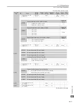
Overtravel
Occurred
There is a mistake in the allo-
cation of the P-OT or N-OT
(Forward Drive Prohibit or
Reverse Drive Prohibit) sig-
nal in Pn50A = n.X
or
Pn50B = n.
X.
Check to see if the P-OT
signal is allocated in
Pn50A = n.X
.
If another signal is allo-
cated in Pn50A
=n.X
, allocate the
P-OT signal instead.
*
Check to see if the N-OT
signal is allocated in
Pn50B = n.
X.
If another signal is allo-
cated in Pn50B
=n.
X, allocate the
N-OT signal instead.
*
The selection of the Servo-
motor stopping method is
not correct.
Check the servo OFF
stopping method set in
Pn001 = n.
X or
Pn001 = n.
X
.
Select a Servomotor
stopping method other
than coasting to a stop.
*
Check the torque control
stopping method set in
Pn001 = n.
X or
Pn001 = n.
X
.
Select a Servomotor
stopping method other
than coasting to a stop.
*
Improper
Stop Posi-
tion for
Overtravel
(OT) Signal
The limit switch position and
dog length are not appropri-
ate.
–
Install the limit switch at
the appropriate posi-
tion.
–
The overtravel limit switch
position is too close for the
coasting distance.
–
Install the overtravel
limit switch at the
appropriate position.
–
Position
Deviation
(without
Alarm)
Noise interference occurred
because of incorrect Encoder
Cable specifications.
Check the Encoder Cable
to see if it satisfies speci-
fications. Use a shielded
twisted-pair wire cable or
a screened twisted-pair
cable with conductors of
at least 0.12 mm
2
.
Use cables that satisfy
the specifications.
–
Noise interference occurred
because the Encoder Cable
is too long.
Check the length of the
Encoder Cable.
•
Rotary Servomotors:
The Encoder Cable
length must be 50 m
max.
•
Linear Servomotors:
Make sure that the
Serial Converter Unit
cable is no longer
than 20 m and that
the Linear Encoder
Cable and the Sensor
Cable are no longer
than 15 m each.
–
Noise interference occurred
because the Encoder Cable
is damaged.
Check the Encoder Cable
to see if it is pinched or
the sheath is damaged.
Replace the Encoder
Cable and correct the
cable installation envi-
ronment.
–
The Encoder Cable was sub-
jected to excessive noise
interference.
Check to see if the
Encoder Cable is bundled
with a high-current line or
installed near a high-cur-
rent line.
Correct the cable lay-
out so that no surge is
applied by high-current
lines.
–
There is variation in the FG
potential because of the
influence of machines on the
Servomotor side, such as a
welder.
Check to see if the
machines are correctly
grounded.
Properly ground the
machines to separate
them from the FG of
the encoder.
–
There is a SERVOPACK
pulse counting error due to
noise.
Check to see if there is
noise interference on the
I/O signal line from the
encoder or Serial Con-
verter Unit.
Implement counter-
measures against noise
for the encoder wiring
or Serial Converter Unit
wiring.
–
Continued on next page.
Continued from previous page.
Problem
Possible Cause
Confirmation
Correction
Reference
Summary of Contents for SERVOPACK Sigma 7 Series
Page 52: ...3 7 Monitoring 3 23 ...