


5.1 FT40 Specification
5.1.3 Troubleshooting Alarms
5-36
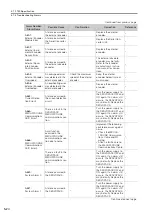
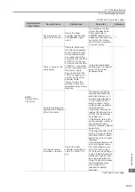
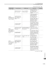
A.E71:
Safety Option
Module Detec-
tion Failure
There is a faulty con-
nection between the
SERVOPACK and the
Safety Option Module.
Check the connection
between the SERVO-
PACK and the Safety
Option Module.
Correctly connect the
Safety Option Module.
–
The Safety Option
Module was discon-
nected.
–
Execute Fn014 (Reset
Option Module Configura-
tion Error) from the Digital
Operator or S
and then turn the power
supply to the SERVO-
PACK OFF and ON again.
*1
A failure occurred in
the Safety Option
Module.
–
Replace the Safety Option
Module.
–
A failure occurred in
the SERVOPACK.
–
Replace the SERVO-
PACK.
–
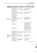
A.E72:
Feedback Option
Module Detec-
tion Failure
There is a faulty con-
nection between the
SERVOPACK and the
Feedback Option
Module.
Check the connection
between the SERVO-
PACK and the Feed-
back Option Module.
Correctly connect the
Feedback Option Module.
–
The Feedback Option
Module was discon-
nected.
–
Reset the Option Module
configuration error and
turn the power supply to
the SERVOPACK OFF and
ON again.
*1
A failure occurred in
the Feedback Option
Module.
–
Replace the Feedback
Option Module.
–
A failure occurred in
the SERVOPACK.
–
Replace the SERVO-
PACK.
–
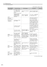
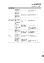
A.E74:
Unsupported
Safety Option
Module
A failure occurred in
the Safety Option
Module.
–
Replace the Safety Option
Module.
–
An unsupported
Safety Option Module
was connected.
Refer to the catalog of
the connected Safety
Option Module.
Connect a compatible
Safety Option Module.
–
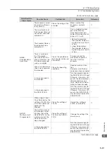
A.Eb1:
Safety Function
Signal Input Tim-
ing Error
The delay between
activation of the
/HWBB1 and
/HWBB2 input sig-
nals for the HWBB
was ten second or
longer.
Measure the time delay
between the /HWBB1
and /HWBB2 signals.
The output signal circuits
or devices for /HWBB1
and /HWBB2 or the SER-
VOPACK input signal cir-
cuits may be faulty.
Alternatively, the input sig-
nal cables may be discon-
nected. Check to see if
any of these items are
faulty or have been dis-
connected.
–
A failure occurred in
the SERVOPACK.
–
Replace the SERVO-
PACK.
–
A.EC8:
Gate Drive Error 1
(An error
occurred in the
gate drive circuit.) A failure occurred in
the SERVOPACK.
–
Turn the power supply to
the SERVOPACK OFF and
ON again. If an alarm still
occurs, the SERVOPACK
may be faulty. Replace the
SERVOPACK.
–
A.EC9:
Gate Drive Error 2
(An error
occurred in the
gate drive circuit.)
Continued on next page.
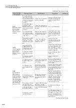
Continued from previous page.
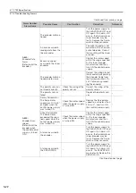
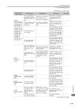
Alarm Number:
Alarm Name
Possible Cause
Confirmation
Correction
Reference
Summary of Contents for SERVOPACK Sigma 7 Series
Page 52: ...3 7 Monitoring 3 23 ...