LUBRICATION SYSTEM
9-10
TNV IDI Service Manual
Trochoid Oil Pump
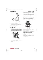
Check Inner Rotor and Gear Boss
Clearance
1 – Crank Gear
2 – Inner Rotor
3 – Inside Width Across Flats of Inner Rotor
4 – Overall Inside Diameter of Inner Rotor
5 – Overall Inside Diameter of Gear Boss
6 – Outside Width Across Flats of Gear Boss
Figure 9-10
Record the measurement.
Gear Boss Clearance on page 9-5 for service
limits.
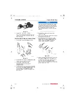
Reassembly of Oil Pump
Figure 9-11
1. Lubricate the outer rotor
(Figure 9-11, (1))
,
inner rotor
(Figure 9-11, (2))
and pump bore in
the gear case cover
(Figure 9-11, (3))
with
clean engine oil.
2. Reinstall the outer rotor in the gear case. The
dot mark on the face of the outer rotor must
face up toward the oil pump cover.
3. Reinstall the inner rotor into the gear case cover
with the dot mark also facing up. Make sure that
the pilot on the back side of the inner rotor fits
into the bore in the gear case cover and the top
surface of the inner rotor is flush with the top
surface of the outer rotor.
4. Reinstall the oil pressure regulator valve
(Figure 9-11, (4))
into the oil pump cover
(Figure 9-11, (5))
. Apply LOCTITE
®
242 (red) to
the valve plug, following the manufacturer’s
instructions.
5. Reinstall the oil pump cover
(Figure 9-11, (5))
.
Apply LOCTITE 290 (green) or LOCTITE 262
(red) to the oil pump cover screws. Tighten the
pump cover screws to 52 - 70 in·lb
(5.9 - 7.9 N·m, 0.6 - 7.9 kgf·m).
6. Reinstall the crankshaft pulley and gear case
cover.
See Removal of Timing Gear Case
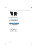
7. Reinstall the engine coolant pump V-pulley
(Figure 9-12, (3))
, spacer
(Figure 9-12, (2))
,
engine cooling fan
(Figure 9-12, (1))
and
engine cooling fan guard (if equipped).
Figure 9-12
8. Reinstall the V-belt. Tighten the V-belt to the
proper tension.
(1)
(3)
(4)
(2)
(6)
(5)
0001976A
(5)
(1)
(2)
(4)
(3)
(1)
(3)
(4)
(2)
0001959B
TNV_IDI_ServiceManual_A4.book 10 ページ 2012年2月24日 金曜日 午前10時24分


