FUEL SYSTEM
TNV IDI Service Manual
7-13
Fuel Injection Pump
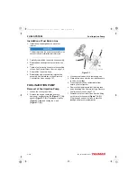
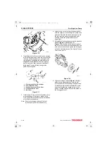
Figure 7-8
8. Remove the fuel supply line
(Figure 7-8, (2))
from the fitting on the fuel injection pump.
9. Plug or cap all openings to minimize leakage
and prevent contamination.
10. Remove the throttle cable
from the fuel injection
pump.
11. Separate the stop solenoid wiring connector
(Figure 7-8, (3))
.
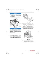
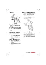
12. Remove the lube oil line
(Figure 7-9, (1))
from
the fuel injection pump and cylinder block.
IMPORTANT
Take care to not damage or bend the lube
oil line.
Figure 7-9
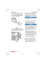
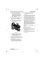
13. Remove the fuel injection pump drive gear
access cover
(Figure 7-10, (1))
from the gear
case cover
(Figure 7-10, (2))
.
Note: The cover is secured with an adhesive
sealant. Use a gasket scraper to
separate the cover from the gear case
cover.
Figure 7-10
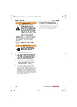
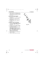
14. To aid in reassembly, make reference marks
(Figure 7-11, (1))
on the drive gear and idler
gear.
0002210
(1)
(3)
(2)
(1)
00022
3
9
(2)
(1)
0002211
TNV_IDI_ServiceManual_A4.book 13 ページ 2012年2月24日 金曜日 午前10時24分


