COOLING SYSTEM
8-8
TNV IDI Service Manual
Engine Coolant Pump
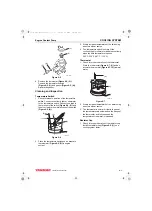
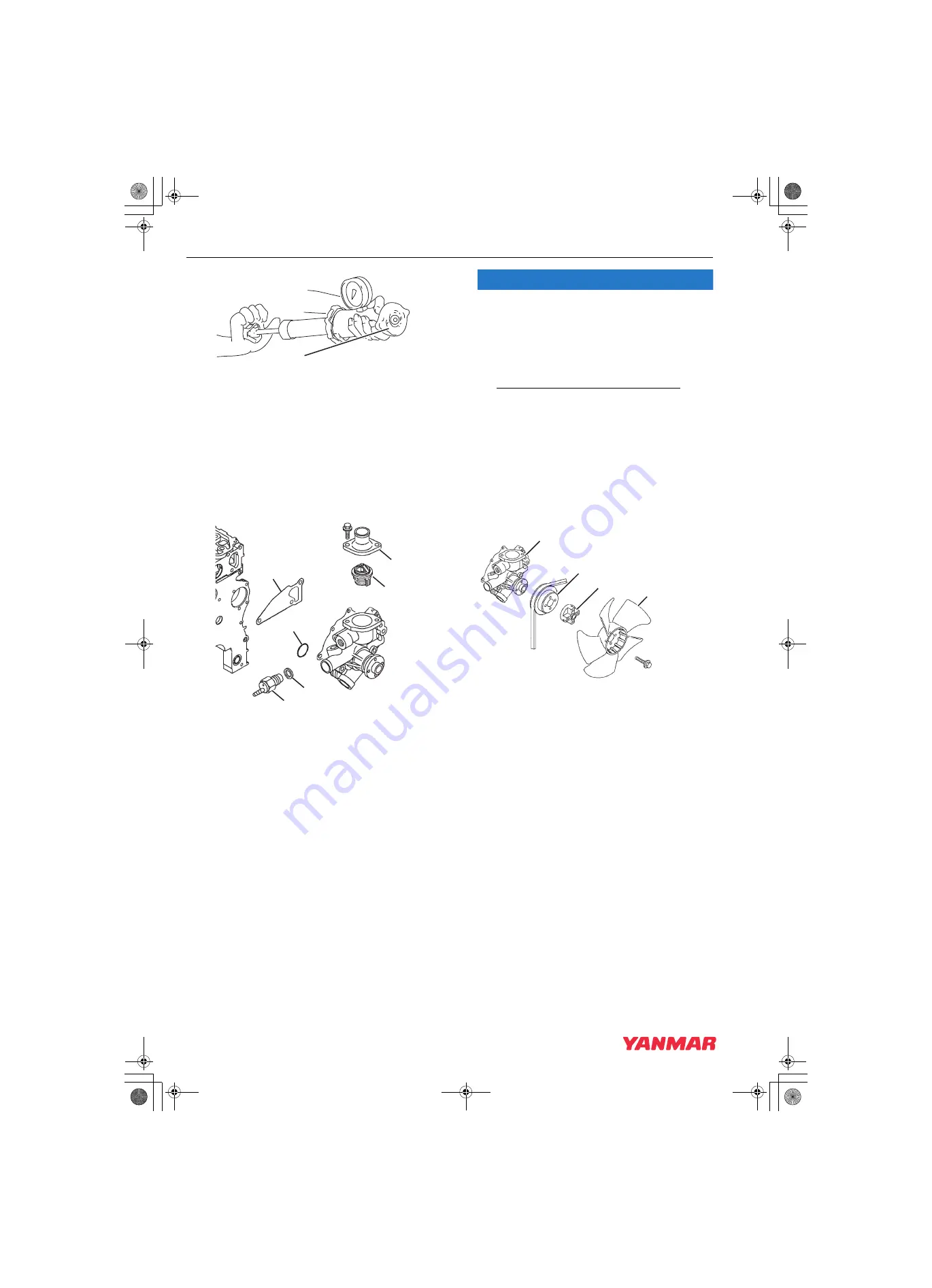
Figure 8-8
2. Apply 10.8 - 14.8 psi (75 - 105 kPa;
0.75 - 1.05 kgf/cm²) to the radiator cap. The
radiator cap relief valve must open within the
specified range.
Reassembly of Engine Coolant Pump
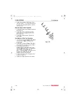
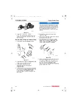
1. Reinstall the thermostat
(Figure 8-9, (1))
.
Figure 8-9
2. Reinstall the thermostat cover
(Figure 8-9, (2))
.
Tighten the thermostat cover bolts.
3. Reinstall the temperature switch
(Figure 8-9, (3))
and a new gasket
(Figure 8-9, (4))
.
4. Position the engine coolant pump on the engine
and install a new gasket
(Figure 8-9, (6))
. Use
a new special O-ring
(Figure 8-9, (5))
on
assembly between the engine coolant pump
and the joint.
NOTICE
Use a new special O-ring between the engine
coolant pump and the joint. Be sure to use the
special O-ring for each engine model. Although
the O-ring dimensions are the same as a
commercially available O-ring, the material is
different.
5. Reinstall the engine coolant pump bolts.
Tighten the bolts.
6. Inspect and reinstall the coolant hoses and the
temperature switch lead wire.
7. Reinstall the engine coolant pump V-pulley
(Figure 8-10, (3))
, spacer
(Figure 8-10, (2))
engine coolant fan
(Figure 8-10, (1))
and
engine
coolant fan guard (if equipped).
Figure 8-10
8. Inspect the condition of the V-belt. There must
be clearance
(Figure 8-11, (1))
between the
V-belt and the bottom of the pulley groove. If
there is no clearance
(Figure 8-11, (2))
between the V-belt and the bottom of the pulley
groove, replace the V-belt.
0000579A
(1)
(5)
(4)
(1)
(2)
(3)
(6)
0001959C
(1)
(3)
(4)
(2)
0001959B
TNV_IDI_ServiceManual_A4.book 8 ページ 2012年2月24日 金曜日 午前10時24分


