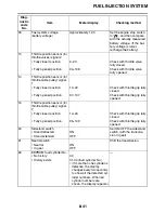
FUEL INJECTION SYSTEM
8-39
41
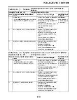
Lean angle sensor:
open or short circuit
detected.
• Open or short circuit in wire harness.
• Defective lean angle sensor.
• Malfunction in ECU.
08
42
No normal signals are
received from the speed
sensor.
• Open circuit in wire harness.
• Malfunction in speed sensor.
• Malfunction in ECU.
07
Neutral switch:
open or short circuit
detected.
• Open circuit in wire harness.
• Malfunction in neutral switch.
• Malfunction in ECU.
21
43
Power supply to the injec-
tors and the fuel pump is
not normal.
• Open or short circuit in wire harness.
• Malfunction in ECU.
09
44
An error is detected while
reading or writing on
EEPROM (CO adjustment
value).
• Malfunction in ECU.
(The CO adjustment value is not properly
written on or read from the internal mem-
ory).
60
46
Power supply is not normal.
Malfunction in the charging system.
Refer to "CHARGING SYSTEM" on page 8-
11.
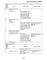
—
50
Faulty ECU memory.
(When this malfunction is
detected in the ECU, the
fault code number might not
appear on the meter.)
• Malfunction in ECU.
(The program and data are not properly
written on or read from the internal mem-
ory.)
—
59
Throttle position sensor (for
throttle cable pulley):
open or short circuit
detected.
Throttle position sensor (for
throttle cable pulley) cou-
pler connection is loose.
• Open or short circuit in wire harness.
• Defective throttle position sensor.
• Improperly installed throttle position sensor.
• Malfunction in ECU.
14
15
60
Throttle servo motor:
open or short circuit
detected.
Defective throttle servo
motor.
Malfunction in ECU (servo
motor driving system).
• Open or short circuit in wire harness.
• Defective throttle servo motor (potentiome-
ter circuit).
• Stuck throttle servo motor (mechanism).
• Stuck throttle servo motor (motor).
• Malfunction in ECU.
01
Er-1
No signals are received
from the ECU.
• Open or short circuit in wire harness.
• Malfunction in meter.
• Malfunction in ECU.
• Defective wire connection of the ECU cou-
pler.
—
Er-2
No signals are received
from the ECU within the
specified duration.
• Improper connection in wire harness.
• Malfunction in meter.
• Malfunction in ECU.
—
Fault
code
No.
Symptom
Probable cause of malfunction
Diagnostic
code No.
Summary of Contents for YZFR1W 2007
Page 1: ...2007 MOTORCYCLE SERVICE MANUAL Model YZFR1W 4C8281972000 4C8281972000...
Page 50: ...LUBRICATION POINTS AND LUBRICANT TYPES 2 22...
Page 53: ...LUBRICATION SYSTEM CHART AND DIAGRAMS 2 25 EAS20410 LUBRICATION DIAGRAMS...
Page 55: ...LUBRICATION SYSTEM CHART AND DIAGRAMS 2 27...
Page 57: ...LUBRICATION SYSTEM CHART AND DIAGRAMS 2 29...
Page 59: ...LUBRICATION SYSTEM CHART AND DIAGRAMS 2 31 A A A A...
Page 60: ...LUBRICATION SYSTEM CHART AND DIAGRAMS 2 32 1 Main axle 2 Oil delivery pipe 3 Drive axle...
Page 61: ...LUBRICATION SYSTEM CHART AND DIAGRAMS 2 33...
Page 62: ...LUBRICATION SYSTEM CHART AND DIAGRAMS 2 34 1 Cylinder head 2 Crankshaft...
Page 63: ...COOLING SYSTEM DIAGRAMS 2 35 EAS20420 COOLING SYSTEM DIAGRAMS...
Page 64: ...COOLING SYSTEM DIAGRAMS 2 36 1 Water pump 2 Radiator 3 Radiator fan...
Page 65: ...COOLING SYSTEM DIAGRAMS 2 37...
Page 66: ...COOLING SYSTEM DIAGRAMS 2 38 1 Radiator cap 2 Radiator 3 Oil cooler 4 Thermostat...
Page 67: ...CABLE ROUTING 2 39 EAS20430 CABLE ROUTING...
Page 69: ...CABLE ROUTING 2 41...
Page 71: ...CABLE ROUTING 2 43...
Page 73: ...CABLE ROUTING 2 45...
Page 75: ...CABLE ROUTING 2 47...
Page 77: ...CABLE ROUTING 2 49...
Page 79: ...CABLE ROUTING 2 51...
Page 81: ...CABLE ROUTING 2 53...
Page 171: ...HANDLEBARS 4 49...
Page 197: ...CHAIN DRIVE 4 75...
Page 200: ...CHECKING THE TRANSMISSION 5 90 INSTALLING THE TRANSMISSION 5 91...
Page 293: ...TRANSMISSION 5 93...
Page 314: ...THROTTLE BODIES 7 8...
Page 317: ...AIR INDUCTION SYSTEM 7 11...
Page 320: ...IGNITION SYSTEM 8 1 EAS27090 IGNITION SYSTEM EAS27110 CIRCUIT DIAGRAM...
Page 324: ...ELECTRIC STARTING SYSTEM 8 5 EAS27160 ELECTRIC STARTING SYSTEM EAS27170 CIRCUIT DIAGRAM...
Page 330: ...CHARGING SYSTEM 8 11 EAS27200 CHARGING SYSTEM EAS27210 CIRCUIT DIAGRAM...
Page 333: ...CHARGING SYSTEM 8 14...
Page 334: ...LIGHTING SYSTEM 8 15 EAS27240 LIGHTING SYSTEM EAS27250 CIRCUIT DIAGRAM...
Page 338: ...SIGNALING SYSTEM 8 19 EAS27270 SIGNALING SYSTEM EAS27280 CIRCUIT DIAGRAM...
Page 344: ...COOLING SYSTEM 8 25 EAS27300 COOLING SYSTEM EAS27310 CIRCUIT DIAGRAM...
Page 347: ...COOLING SYSTEM 8 28...
Page 348: ...FUEL INJECTION SYSTEM 8 29 EAS27330 FUEL INJECTION SYSTEM EAS27340 CIRCUIT DIAGRAM...
Page 384: ...FUEL PUMP SYSTEM 8 65 EAS27550 FUEL PUMP SYSTEM EAS27560 CIRCUIT DIAGRAM...
Page 388: ...IMMOBILIZER SYSTEM 8 69 EAS27640 IMMOBILIZER SYSTEM EAS27650 CIRCUIT DIAGRAM...
Page 396: ...ELECTRICAL COMPONENTS 8 77 EAS27970 ELECTRICAL COMPONENTS...
Page 398: ...ELECTRICAL COMPONENTS 8 79...
Page 400: ...ELECTRICAL COMPONENTS 8 81 EAS27980 CHECKING THE SWITCHES...
Page 420: ...ELECTRICAL COMPONENTS 8 101...
Page 429: ...Yamaha Motor Canada Ltd 480 Gordon Baker Road Toronto ON M2H 3B4...


