6-13
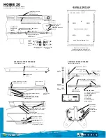
Impeller, drive shaft, and impeller duct
2.
Install a new ball bearing “1” onto the drive
shaft “2”.
3.
Install the drive shaft “1” (along with the
ball bearing “2”) and spacer “3”.
4.
Apply EPNOC grease AP #0 to the space
between the drive shaft “1” and the spacer
“2”.
5.
Install a new ball bearing “1”.
A. Worldwide
B. U.S.A. and Canada
Oil seal installer attachment “3”
90890-06733
Oil seal installer attachment “4”
YW-06628
Distance “a”
7.0 ± 0.2 mm (0.28 ± 0.008 in)
Bearing attachment “3”
90890-06728
Bearing attachment “3”
YW-06728
Distance “a”
23.0 ± 0.1 mm (0.91 ± 0.004 in)
A
3
a
1
2
A
B
4
a
1
2
A
3
1
a
2
Bearing attachment “4”
90890-06728
Bearing attachment “4”
YW-06728
Grease quantity
20 g (0.7 oz)
Bearing attachment “2”
90890-06728
Bearing attachment “2”
YW-06728
4
2
1
3
2
1
1
1
2
Summary of Contents for WaveRunner VXR VX1800A
Page 1: ...SERVICE MANUAL WaveRunner VXS VX1800 F2W VXR VX1800A F2W F2W 28197 ZU 11 ...
Page 12: ...How to use this manual 1 7 UP Upside YDIS Yamaha Diagnostic System Abbreviation Description ...
Page 40: ...Technical tips 1 35 MEMO ...
Page 163: ...Oil separator tank and oil pan 5 72 3 4 4 4 4 4 9 4 1 5 6 10 11 7 2 3 8 ...
Page 180: ...Crankcase connecting rod and piston 5 89 MEMO ...
Page 204: ...6 23 Intermediate housing Intermediate housing bolt 2 17 Nm 1 7 kgf m 12 5 ft lb 1 2 3 ...
Page 205: ...Intermediate housing 6 24 MEMO ...
Page 251: ...Indication system 7 44 MEMO ...
Page 278: ...8 25 Exhaust system 6 Install the band Rubber hose clamp 2 3 5 Nm 0 35 kgf m 2 58 ft lb ...
Page 290: ...Deck and hull 8 37 MEMO ...
Page 312: ...Engine unit troubleshooting 9 21 MEMO ...
Page 313: ...A Appendix Wiring diagram A 1 How to use the wiring diagram A 1 VXS VXR A 2 ...
Page 317: ......
Page 318: ...Mar 2015 CR E ...


