
4
Replacement
4-14
t
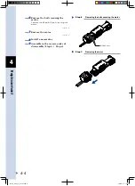
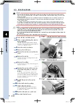
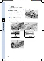
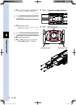
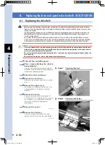
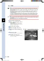
Remove the motor.
Remove the screws (4) securing the motor
and remove the motor. At this time, be
careful not to allow the ball screw shaft to
come out of the nut.
Removing the motor
Step 15
<N15>
<N18>
Nut section
Ball screw
53410-AA-00
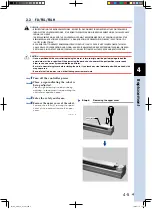
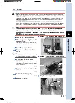
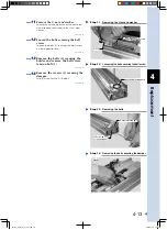
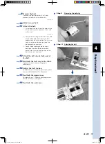
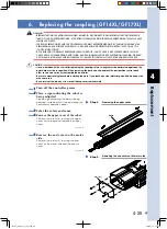
Cautions on motor removal work
Step 15
Allow a space of
300mm or more.
Wall
Ball screw
(Do not pull out.)
Nut section
53411-AA-00
y
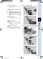
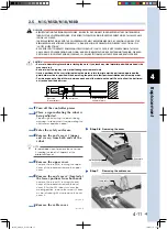
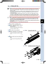
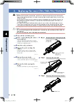
Install a new motor.
Tighten the bolts to the following torque.
Robot
Bolt
Tightening torque
N15
Hex socket-head bolt
(M5)
60kgf•cm to 90kgf•cm
N18
Hex socket-head bolt
(M6)
100kgf•cm to 130kgf•cm
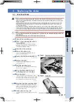
u
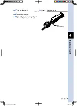
Assemble in the reverse order of
disassembly.
Proceed while making sure the positional
relation and assembly order of the parts are
correct.
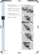
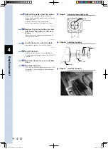
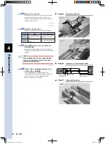
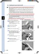
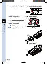
c
CAUTION
When installing the ball screw, apply the proper
amount of molybdenum grease to the clamp
portion (see photo below).
Applying the grease
Step 17
Apply molybdenum
grease here.
<N15>
53412-AA-00
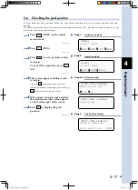
i
Adjust the coupling position and
secure the coupling.
After replacing the motor, adjust the
coupling position so that the grid position is
within 50±20%, which is displayed by
performing return-to-origin.
FLIP-X_maint_E_V1.50.indb 14
18/05/15 15:01
Summary of Contents for FLIP-X Series
Page 2: ...FLIP X_maint_E_V1 50 indb 2 18 05 15 15 00...
Page 40: ...FLIP X_maint_E_V1 50 indb 2 18 05 15 15 01...
Page 41: ...Chapter 1 Overview Contents 1 Overview 1 1 FLIP X_maint_E_V1 50 indb 1 18 05 15 15 01...
Page 42: ...FLIP X_maint_E_V1 50 indb 2 18 05 15 15 01...
Page 44: ...FLIP X_maint_E_V1 50 indb 2 18 05 15 15 01...
Page 46: ...FLIP X_maint_E_V1 50 indb 2 18 05 15 15 01...
Page 60: ...FLIP X_maint_E_V1 50 indb 2 18 05 15 15 01...
Page 72: ...FLIP X_maint_E_V1 50 indb 12 18 05 15 15 01...
Page 74: ...FLIP X_maint_E_V1 50 indb 2 18 05 15 15 01...
Page 104: ...FLIP X_maint_E_V1 50 indb 2 18 05 15 15 01...


