4
Replacement
4-12
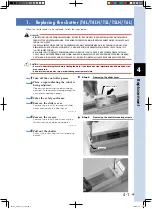
8
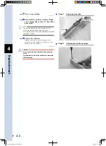
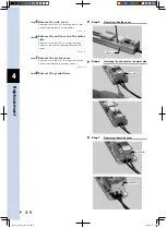
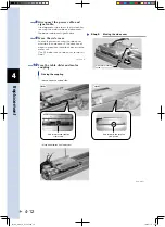
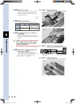
Disconnect the power cable and
signal cable.
Use diagonal cutters to cut the insulock-ties
securing the motor cable and disconnect
the power cable and signal cable.
9
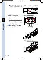
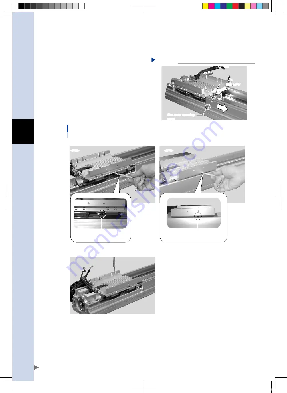
Move the side cover.
Loosen the screw securing the side cover
and slide the side cover in the direction of
arrow to a position that allows access to the
motor unit.
(The N18 robot has no side cover, so skip this
Step.)
Moving the side cover
Step 9
Side cover
Side cover mounting
screw
53404-AA-00
0
Free the table slider and motor
coupling.
Freeing the coupling
<N15>
<N18>
Hole for motor-and-coupling
clamp screw
Hole for motor-and-coupling
clamp screw
• When workpiece is on table slider
• When no workpiece is on table slider
53405-AA-00
FLIP-X_maint_E_V1.50.indb 12
18/05/15 15:01
Summary of Contents for FLIP-X Series
Page 2: ...FLIP X_maint_E_V1 50 indb 2 18 05 15 15 00...
Page 40: ...FLIP X_maint_E_V1 50 indb 2 18 05 15 15 01...
Page 41: ...Chapter 1 Overview Contents 1 Overview 1 1 FLIP X_maint_E_V1 50 indb 1 18 05 15 15 01...
Page 42: ...FLIP X_maint_E_V1 50 indb 2 18 05 15 15 01...
Page 44: ...FLIP X_maint_E_V1 50 indb 2 18 05 15 15 01...
Page 46: ...FLIP X_maint_E_V1 50 indb 2 18 05 15 15 01...
Page 60: ...FLIP X_maint_E_V1 50 indb 2 18 05 15 15 01...
Page 72: ...FLIP X_maint_E_V1 50 indb 12 18 05 15 15 01...
Page 74: ...FLIP X_maint_E_V1 50 indb 2 18 05 15 15 01...
Page 104: ...FLIP X_maint_E_V1 50 indb 2 18 05 15 15 01...

