5
W
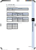
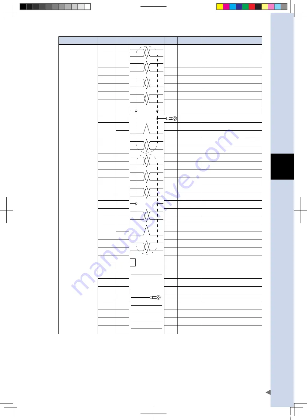
iring specifications
5-17
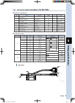
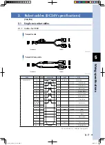
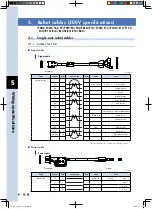
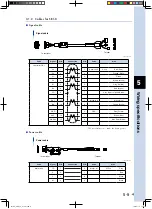
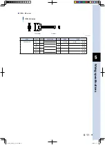
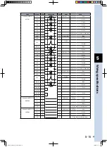
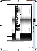
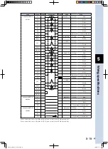
Parts
Signal
PIN
Connection
PIN
Parts
Wire
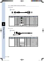
Controller ROB I/O
S+
1
1
Linear: P1
0.3sq
Red
XY(ZR)
S-
2
2
White
C+
3
3
Green
C-
4
4
White
Z+
10
5
Yellow
Z-
11
6
White
+5V
6
7
Blue
DG
5
8
White
FG
7
9
Drain wire Grey (Heat shrinkable tube)
FG
0.75sq
Gray
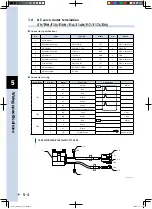
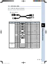
24V
ORG1
0.3sq
9
1
Purple
ORG
12
2
Blue
GND24
13
3
Brown
S2
19
1
Resolver: P2
Red
S4
20
2
White
S1
21
3
Green
S3
22
4
White
R1
23
5
Yellow
R2
24
6
White
FG
25
7
Drain wire Grey (Heat shrinkable tube)
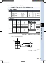
MB+
32
1
Brake: BK2
0.3sq
Blue
MB-
34
2
White
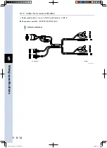
24V
ORG2
27
1
Purple
ORG
30
2
Blue
GND24
31
3
Brown
HLIM
28
0.3sq
Gray
GND24
29
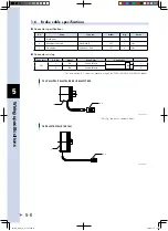
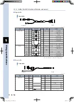
Controller MOTOR
U
2
1
Motor: M1
0.75sq
Red
XM(ZM)
V
3
2
White
W
4
3
Black
FG
1
Grey (Heat shrinkable tube)
Controller MOTOR
U
2
1
Motor: M2
0.75sq
Red
YM(RM)
V
3
2
White
W
4
3
Black
FG
1
4
Grey (Heat shrinkable tube)
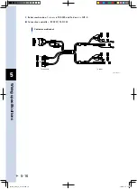
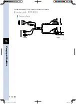
When connected to the XY of the ROB I/O, connect to the MOTOR XM and YM.
When connected to the ZR of the ROB I/O, connect to the MOTOR ZM and RM.
FLIP-X_maint_E_V1.50.indb 17
18/05/15 15:01
Summary of Contents for FLIP-X Series
Page 2: ...FLIP X_maint_E_V1 50 indb 2 18 05 15 15 00...
Page 40: ...FLIP X_maint_E_V1 50 indb 2 18 05 15 15 01...
Page 41: ...Chapter 1 Overview Contents 1 Overview 1 1 FLIP X_maint_E_V1 50 indb 1 18 05 15 15 01...
Page 42: ...FLIP X_maint_E_V1 50 indb 2 18 05 15 15 01...
Page 44: ...FLIP X_maint_E_V1 50 indb 2 18 05 15 15 01...
Page 46: ...FLIP X_maint_E_V1 50 indb 2 18 05 15 15 01...
Page 60: ...FLIP X_maint_E_V1 50 indb 2 18 05 15 15 01...
Page 72: ...FLIP X_maint_E_V1 50 indb 12 18 05 15 15 01...
Page 74: ...FLIP X_maint_E_V1 50 indb 2 18 05 15 15 01...
Page 104: ...FLIP X_maint_E_V1 50 indb 2 18 05 15 15 01...


