background image


8


1

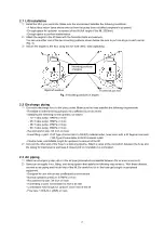
 When filling the delivery piping with material for the first time, the air inside the piping will blow out. Please follow 

the following procedure. 

Put a plastic bag over the material outlet to receive discharged material. 

Open the valve on the delivery piping.


Open the air valve for the pump and set the pump air regulator for minimum operating pressure.


The pump will start discharging material from the outlet. Once the air in the piping is released completely, 
close the air valve for the pump and set the pump air regulator to 0MPa.


The pump is now ready for operation.


2

 Adjust the pump air regulator to set to the desirable operating pressure. An estimate of the material discharge 

pressure to the supply air pressure is calculated by “supply air pressure × pump ratio”.   
(e.g. When operating a 38:1 ratio pump at 0.7MPa supply air pressure, material will be discharged at approx. 
26.6MPa.) 


<NOTE> 

Material viscosity changes with seasons. It is recommended to make a note of appropriate pressure for each 

season. 


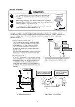
3.4  Replacement of drum 

CAUTION 

Do not try to separate the inductor plate from a drum at once with the “PRESS” button depressed. 
Compressed air built up inside a drum may be released causing a spurt of residual material. 


1

 When a drum becomes empty, the pump will run dry and NOT stop automatically. Close the pump air valve and 

adjust air pressure to 0MPa using the pump air regulator. 

2

 Verify that the lift control switch is set to “DOWN” and the air release plug on the inductor plate is closed. 
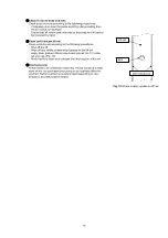
3

 Keep holding the “AIR” button until the inductor plate reaches 10cm below the point where it is separated from a 

drum. The inductor plate sometimes separates automatically from a drum. If it doesn’t, press and release the 
“AIR” button repeatedly to separate the inductor plate gradually from a drum. 

4

 Once the inductor plate is separated from a drum, turn the switch to “UP” to raise the lift to the upper limit. 

5

 Set a new drum according to the procedure described in “3.2 Placement of drum”. 


3.5 After work 

CAUTION 

After work or when shutting down the unit for a long period, be sure to turn off the air supply source 
to disconnect air supply to the pump, and open the valves on the material outlet or gun to release 
residual pressure inside the pump and piping. Failure to shut off air may cause damage to the hoses 
and pipes and/or leak in the valves and gun. Any secondary accidents caused by the failure 
mentioned above are the responsibility of the users. 


1

 Close the air valve for the pump and set the pump air regulator to 0MPa. 

2

 Adjust the lift control switch to “DOWN”. 


Summary of Contents for 140 Series

Page 1: ...P25PDAL MODEL No 881113 SR140P38PDAL MODEL No 881114 SR140P50PDAL MODEL No 881115 SR125D13DAL MODEL No 881125 WARNING Prior to operating this pump be sure to read this operation manual for safety Afte...

Page 2: ...ng of its contents Keep this manual carefully in an easy to access place so that the user may refer to it whenever necessary Warnings and Cautions To use this product safely be sure to observe the con...

Page 3: ...e specified in this manual may result in personal injury or property damage Be sure to use the unit in accordance with the specifications described in 6 Specifications in this manual Installation and...

Page 4: ...he requirements for location and material pressure resistance and size of hoses and other device avoiding lift operation failure and pipe leakage or breakage Do not plumb directly Do not connect the m...

Page 5: ...Connecting the ground wire 5 3 Operating Method 5 3 1 Description of control and valve 6 3 2 Placement of drum 7 3 3 Operation 7 3 4 Replacement of drum 8 3 5 After work 8 4 Maintenance and Inspectio...

Page 6: ...names Fig 1 and Fig 2 show the names of each part used in the instructions in this manual Use them as a reference Fig 1 Part names Air release hole socket attached under air release plug Eye nut Rc1...

Page 7: ...ful not to allow the sealing materials to enter the piping Do not apply the tip of the terminal two thread ridges to maintain conductive property of the ground However no applying is necessary if it w...

Page 8: ...e 3 4 inch or more Hose fitting or joint 140 Type Connectable to G3 4 F material outlet hose union with a 30 degree male seat 125 Type Connectable to Rc3 4 material outlet Flexible hose comfortable le...

Page 9: ...g pump to inductor plate Insert the lower part of the pump through the gasket into the inductor plate Rotate the holes in the gasket and flanged part of the pump to align with the bolt holes in the in...

Page 10: ...ed the maximum operating pressure of the pump 0 7MPa Overpressure may cause a product failure resulting in serious personal injury and or property damage Do not exceed the maximum operating pressure o...

Page 11: ...ntained at a constant level by the throttle valves attached on the air inlet of the air cylinder of the lift To operate Adjust the switch to each position depending on the intended use PRESS button Li...

Page 12: ...operating at approx 0 05MPa Adjust the pump air regulator to set pump speed to 5 8 seconds per cycle Keep pressing the PRESS button until material comes out of the bleeder valve Once material comes ou...

Page 13: ...ed causing a spurt of residual material 1 When a drum becomes empty the pump will run dry and NOT stop automatically Close the pump air valve and adjust air pressure to 0MPa using the pump air regulat...

Page 14: ...art of the pump or air material piping There is no abnormal noise during pump operation and There is no abrasion or deterioration apparently in each part of the pump Inspect operation of lift Inspect...

Page 15: ...procedures Shut off the lift Wipe off any visible contaminated grease on the lift rail Apply clean grease lithium soap based grease No 1 to slide rail grooves Fig 10 Move the lift to clean and lubric...

Page 16: ...nd lower pump is completely separated from air motor In this case parts inside of lower pump may be damaged Inspect inside lower pump first then replace damaged part and retighten each part Leak occur...

Page 17: ...during operation 2 Lift The plastic tubes will be degraded naturally Replace them all every six years The switches and regulators should be replaced if you find they are not working properly Never use...

Page 18: ...13 5 Parts Disassembly Drawing and Parts List Parts Disassembly Drawing...

Page 19: ...Plain washer 14 1 31 631014 Plain washer 4 1 32 619151 Bolt 4 1 33 602702 Screw 4 1 34 619075 Bolt 16 1 35 631417 Spring washer 16 2 854560 854561 854562 854664 Pump assembly 1 4 804823 Inductor plate...

Page 20: ...15 804822 OPERATION PANEL ASSEMBLY...

Page 21: ...E 0 60 C 0 80 C MAXIMUM OPERATING NOISE APPLICABLE CONTAINERS Equivalent to JIS Z 1600 Open Head Steel Drums drums type A and C and D SUPPLY AIR PRESSURE MAXIMUM VALUE OF PAIL LIFT 1 0 MPa 145 psi RAN...

Page 22: ...cause corrosion inflation or dissolution of the component parts of the product 4 Irregularity arising from repair made by other than by our firm our regional office dealer or authorized service perso...

Page 23: ......

Page 24: ...8504 Japan PHONE 81 0 3 3777 0241 FAX 81 0 3 3777 0584 E mail intl yamadacorp co jp Web www yamadacorp co jp YAMADA THAILAND CO LTD 41 79 Moo 6 Bangcha long Bangplee Sumutprakarn10540 Thailand PHONE 6...

Reviews: