

11
PROBLEM
POSSIBLE CAUSE
REMEDY
Compressor is off.
Turn on compressor.
Valve on air piping is closed.
Open valve.
Air pressure setting is under 0.2MPa.
Set air pressure to 0.2MPa or above.
Valve on material outlet is closed.
Open valve.
Frost occurs inside silencer.
Use dry air.
O ring on sliding part of air piston is worn out.
(Air leak occurs from silencer.)
Block (773210) and ball (686271) in valve body (804815) are worn out.
Any parts (e.g. spring, pin) used in switching system in valve body (804815) or
air motor (804814 / 804856) are damaged.
Air leak from air
motor
- Fasteners are loose.
- O rings and packings are worn out.
- Retighten loose parts.
- Replace worn part.
Air leak from
silencer during
shutdown
- Foreign object is caught between block (773210) and valve seat (716246) in
valve body (804815).
- Seating part is worn out.
- Remove foreign object.
- Replace worn part.
Pump doesn’t run
and air leaks from
silencer
- Foreign object is caught between spindle (716299) and valve switcher
(832996) in air motor (804814 / 804856).
- There exists damage that prevents sliding movement of parts below.
- Remove foreign object.
- Replace worn part.
Pump doesn’t draw
material at first time
of operation
Pump operating speed is so fast that lower pump suction cannot keep up with
pump movement. (Valve inside lower pump is not working well.)
Set pump speed to 5-8 sec. per cycle
until material is pumped out.
If upward movement of plunger is faster,
- seat surface of piston valve is defective (wear of seat surface, inclusion of
foreign material) or,
- packings are damaged.
If downward movement of plunger is faster,
- seat surface of foot valve is defective (wear of seat surface, inclusion of foreign
material),
- packings are damaged, or
- shovel rod is bent.
If downward movement of plunger is faster, operating speed is so fast that lower
pump suction cannot keep up with pump movement. (Vacuum is caused inside
lower pump.)
Decrease air pressure until material
comes out. (This pressure is the
upper limit of normal operating
pressure.)
Connecting rod connecting air motor and lower pump is completely separated
from air motor. (In this case, parts inside of lower pump may be damaged.)
Inspect inside lower pump first, then
replace damaged part, and retighten
each part.
Leak occurs in delivery pipe.
Leak occurs in lower pump (connections are loosened or o ring, backup ring, or
packing is damaged).
Material leak from
lower pump
- Fasteners are loose.
- O ring, backup ring, or packing is damaged.
- Retighten loosened parts.
- Replace damaged part.
Internal diameter of drum is larger than specified.
Use the drums described in the
“6.Specifications”.
Air release plug is loosened.
Secure air release plug.
Packing of inductor plate is deteriorated.
Replace packing.
- Fasteners are loosened.
- O ring or backup ring is damaged.
- Retighten loosened parts.
- Replace damaged part.
Internal diameter of drum is larger than specified.
Use the drums described in the
“6.Specifications”.
Drum surface is uneven.
Use straight side drum.
Packing of inductor plate is deteriorated.
Replace packing.
Compressor is off.
Turn on compressor.
Air supply is off.
Turn on air supply.
Valve on air piping is closed.
Open valve.
Air pressure setting is not enough.
Set air pressure to 0.4MPa.
Drum surface is uneven.
Use straight side drum.
Cylindrical section of lift air cylinder is dent.
Replace part.
Foreign object is caught in sliding part of lift.
Foreign object is caught in slider roller of lift rail.
Drum raises
together with lift
Lift control switch is adjusted to “UP”.
Adjust switch to “DOWN”.
Lift control switch is adjusted to “STOP”.
Adjust switch to “DOWN”.
Air release plug on inductor plate is not secured.
Tighten air release plug.
Lift doesn’t raise
with AIR button
Lift doesn’t move
up/down
- Retighten loosened parts.
- Replace damaged part.
Material leak
around inductor
plate
Pump doesn’t stop
- Remove foreign object.
- Replace worn part.
Pump doesn’t run
Remove foreign object.
Replace worn out or damaged part.
Material cannot be
pumped out
Material contains
air bubbles even
after bleeding
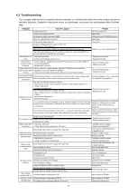
4.2 Troubleshooting
If you suspect that you have a problem with your product, consult the table below for some common problems
and their solutions. Contact the retail store where you purchased your product or our business office if all else
fails.


