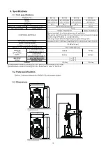
background image


12

Application

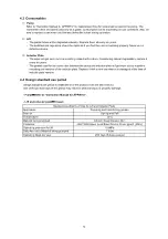
Pumping and transferring grease

Season

Spring and Fall

Temperature

20°C

Material being pumped

Lithium Soap Grease: No.1

Container

JIS Z 1600 Open Head Steel Drums, Drum type D (208L)

Operating pressure for lift

0.4MPa

Daily Amount of Material being pumped

1 drum

Operating Days per year

260 days (5 days a week)

Standard Conditions of Use for Lift and Inductor Plate

4.3 Consumables 

1


Pump 

Refer to “Instruction Manual for APP067U” for replacement time for consumables used in the pump. The 
replacement time should be used only as a guide. Consumption varies depending on use conditions. Also, be 
sure to replace a part when you find any defect like a leak during operation.


2


Lift 

-  The plastic tubes will be degraded naturally. Replace them all every six years. 
-  The switches and regulators should be replaced if you find they are not working properly. Never use a 

defective device. 


3


Inductor Plate 

-  The wiper will get worn out due to sliding contact with a drum. Considering natural degradation, replace it 

every six years. 

-  The gasket used for the connection between the pump and inductor plate will get worn out by repetitive 

mounting and removal of the inductor plate. Replace it with a new one when it is damaged at the time of 
inductor plate removal. 


4.4  Design standard use period 

Design standard use period is established for the product. (See the table below.) 
Use of the product beyond this period may result in personal injury or property damage. 
 

- Pump

Refer to “Instruction Manual for APP067U”. 


- Lift and inductor plate

10years 


Summary of Contents for 140 Series

Page 1: ...P25PDAL MODEL No 881113 SR140P38PDAL MODEL No 881114 SR140P50PDAL MODEL No 881115 SR125D13DAL MODEL No 881125 WARNING Prior to operating this pump be sure to read this operation manual for safety Afte...

Page 2: ...ng of its contents Keep this manual carefully in an easy to access place so that the user may refer to it whenever necessary Warnings and Cautions To use this product safely be sure to observe the con...

Page 3: ...e specified in this manual may result in personal injury or property damage Be sure to use the unit in accordance with the specifications described in 6 Specifications in this manual Installation and...

Page 4: ...he requirements for location and material pressure resistance and size of hoses and other device avoiding lift operation failure and pipe leakage or breakage Do not plumb directly Do not connect the m...

Page 5: ...Connecting the ground wire 5 3 Operating Method 5 3 1 Description of control and valve 6 3 2 Placement of drum 7 3 3 Operation 7 3 4 Replacement of drum 8 3 5 After work 8 4 Maintenance and Inspectio...

Page 6: ...names Fig 1 and Fig 2 show the names of each part used in the instructions in this manual Use them as a reference Fig 1 Part names Air release hole socket attached under air release plug Eye nut Rc1...

Page 7: ...ful not to allow the sealing materials to enter the piping Do not apply the tip of the terminal two thread ridges to maintain conductive property of the ground However no applying is necessary if it w...

Page 8: ...e 3 4 inch or more Hose fitting or joint 140 Type Connectable to G3 4 F material outlet hose union with a 30 degree male seat 125 Type Connectable to Rc3 4 material outlet Flexible hose comfortable le...

Page 9: ...g pump to inductor plate Insert the lower part of the pump through the gasket into the inductor plate Rotate the holes in the gasket and flanged part of the pump to align with the bolt holes in the in...

Page 10: ...ed the maximum operating pressure of the pump 0 7MPa Overpressure may cause a product failure resulting in serious personal injury and or property damage Do not exceed the maximum operating pressure o...

Page 11: ...ntained at a constant level by the throttle valves attached on the air inlet of the air cylinder of the lift To operate Adjust the switch to each position depending on the intended use PRESS button Li...

Page 12: ...operating at approx 0 05MPa Adjust the pump air regulator to set pump speed to 5 8 seconds per cycle Keep pressing the PRESS button until material comes out of the bleeder valve Once material comes ou...

Page 13: ...ed causing a spurt of residual material 1 When a drum becomes empty the pump will run dry and NOT stop automatically Close the pump air valve and adjust air pressure to 0MPa using the pump air regulat...

Page 14: ...art of the pump or air material piping There is no abnormal noise during pump operation and There is no abrasion or deterioration apparently in each part of the pump Inspect operation of lift Inspect...

Page 15: ...procedures Shut off the lift Wipe off any visible contaminated grease on the lift rail Apply clean grease lithium soap based grease No 1 to slide rail grooves Fig 10 Move the lift to clean and lubric...

Page 16: ...nd lower pump is completely separated from air motor In this case parts inside of lower pump may be damaged Inspect inside lower pump first then replace damaged part and retighten each part Leak occur...

Page 17: ...during operation 2 Lift The plastic tubes will be degraded naturally Replace them all every six years The switches and regulators should be replaced if you find they are not working properly Never use...

Page 18: ...13 5 Parts Disassembly Drawing and Parts List Parts Disassembly Drawing...

Page 19: ...Plain washer 14 1 31 631014 Plain washer 4 1 32 619151 Bolt 4 1 33 602702 Screw 4 1 34 619075 Bolt 16 1 35 631417 Spring washer 16 2 854560 854561 854562 854664 Pump assembly 1 4 804823 Inductor plate...

Page 20: ...15 804822 OPERATION PANEL ASSEMBLY...

Page 21: ...E 0 60 C 0 80 C MAXIMUM OPERATING NOISE APPLICABLE CONTAINERS Equivalent to JIS Z 1600 Open Head Steel Drums drums type A and C and D SUPPLY AIR PRESSURE MAXIMUM VALUE OF PAIL LIFT 1 0 MPa 145 psi RAN...

Page 22: ...cause corrosion inflation or dissolution of the component parts of the product 4 Irregularity arising from repair made by other than by our firm our regional office dealer or authorized service perso...

Page 23: ......

Page 24: ...8504 Japan PHONE 81 0 3 3777 0241 FAX 81 0 3 3777 0584 E mail intl yamadacorp co jp Web www yamadacorp co jp YAMADA THAILAND CO LTD 41 79 Moo 6 Bangcha long Bangplee Sumutprakarn10540 Thailand PHONE 6...

Reviews: