4
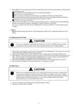
Pump
Bolt
Gasket
Inductor plate
2.4 Pump installation
CAUTION
-
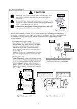
Total weight of the pump and inductor plate is more than 60kg. Use a
chain block for installation to prevent injury. Be very careful during
installation.
-
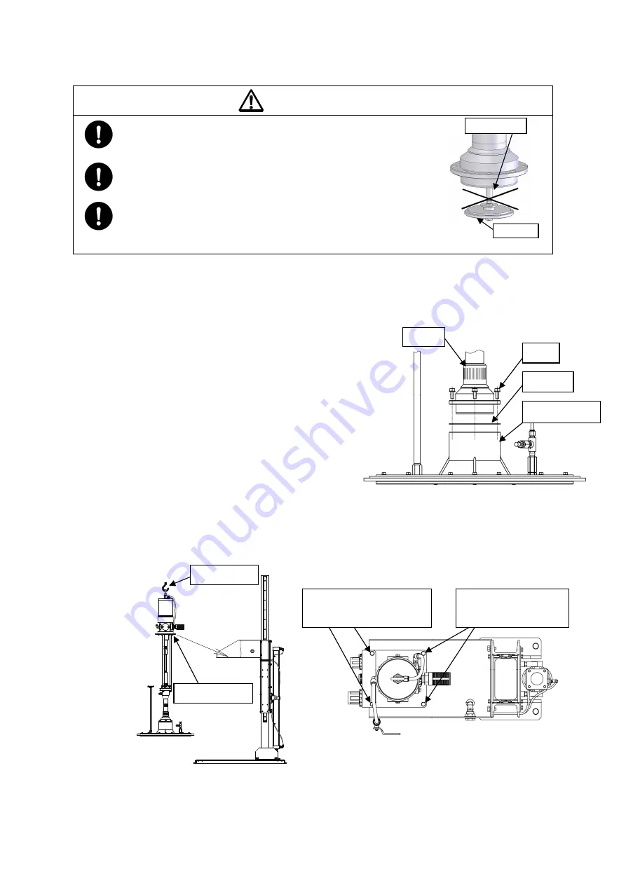
Before installing the pump, verify that the shovel at the bottom is NOT
sticking out. Failure to follow this instruction may result in damage to the
shovel rod causing a pump failure. (Fig. 4)
-
Do not put your hand between the pump body and shovel. Hand injury
may be caused by a sudden movement. (Fig. 4)
Normally, the product is delivered with the pump already installed. If you have dismounted the pump for
maintenance or replacement, mount it again according to the following procedure. The lift is compatible with
any of the following pumps: SR140P25-D (854560), SR140P38-D (854561), SR140P50-D (854562),
SR125D13(854664)
①
Connecting pump to inductor plate
Insert the lower part of the pump through the gasket
into the inductor plate. Rotate the holes in the gasket
and flanged part of the pump to align with the bolt
holes in the inductor plate. Insert bolts with wave
spring washers through each hole and tighten them
securely. (Fig. 5)
Make sure the air release plug is positioned in the front
side of the pump facing away from the bleeder valve.
②
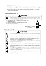
Mounting pump on lift
Lift the pump together with the inductor plate using the
eye nut on the top. Put the mounting plate of the pump
on the pump bracket of the lift. Align the holes on the
mounting plate with the screw holes on the pump
bracket. Insert two bolts with wave spring washers on
the back side of the pump and tighten them temporally.
(Fig. 6 and 7)
Fig. 5
Connecting pump to inductor plate
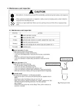
Fig. 4
Shovel part
Shovel
Shovel rod
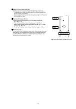
Fig. 6
Mounting pump on lift
Fig. 7
View on arrow A in Fig. 6
Two bolts on the back
side of the pump
Mount the operation panel
first and then insert bolts.
Lifting point
Mounting plate
↓
A

