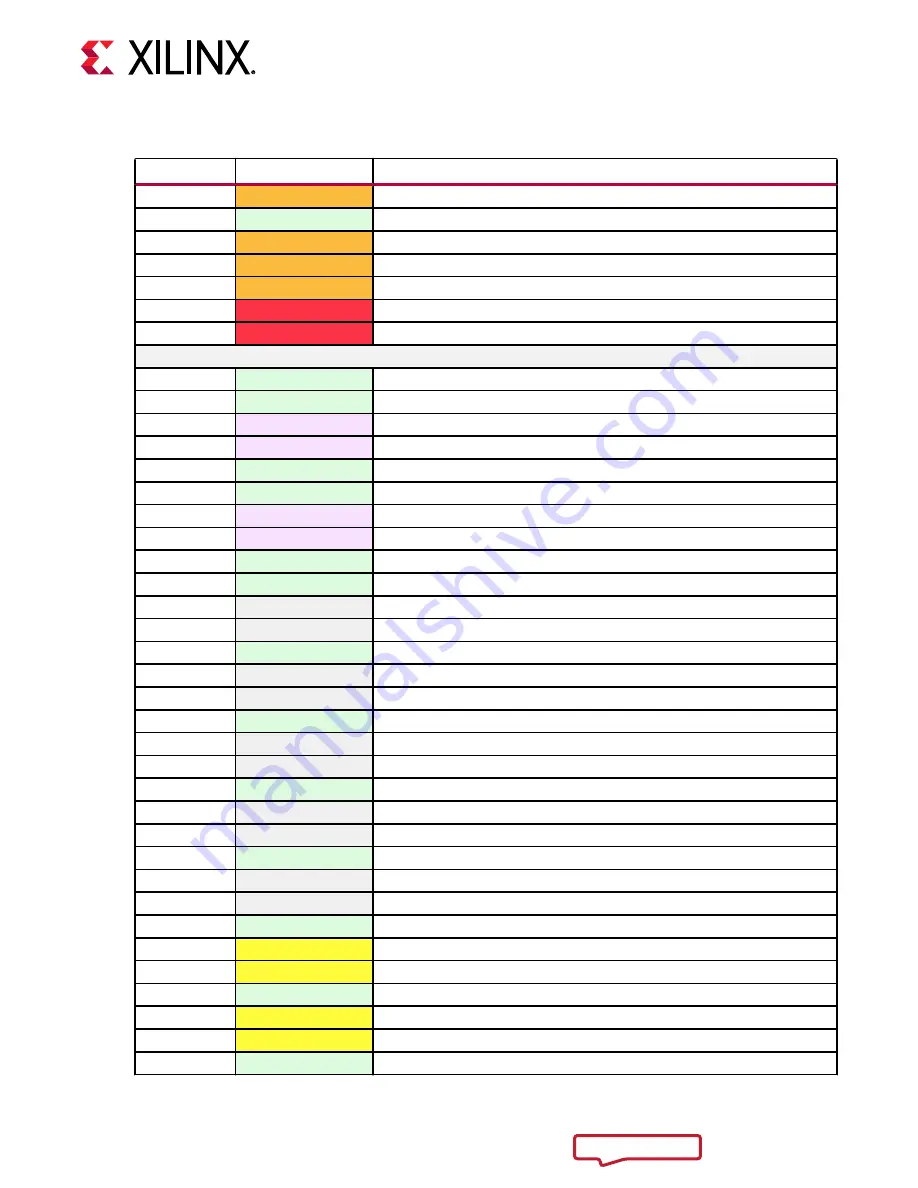
Table 6: SOM240_2 Signal Pins (cont'd)
Pin Number
Signal Name
Signal Description
B54
HDC14
HDIO on bank 44
B55
GND
Ground
B56
HDC15
HDIO on bank 44
B57
HDC16_CC
HDIO clock-capable pin on bank 44
B58
HDC17
HDIO on bank 44
B59
VCCO_HDB
HDB I/O voltage rail, 1.2V to 3.3V
B60
VCCO_HDB
HDB I/O voltage rail, 1.2V to 3.3V
Connector Row C
C1
GND
Ground
C2
GND
Ground
C3
GTH_REFCLK0_C2M_P
GTH REFCLK0 input
C4
GTH_REFCLK0_C2M_N
GTH REFCLK0 input
C5
GND
Ground
C6
GND
Ground
C7
GTH_DP1_M2C_P
GTH Lane 1 TX
C8
GTH_DP1_M2C_N
GTH Lane 1 TX
C9
GND
Ground
C10
GND
Ground
C11
HPB09_P
HPIO on bank 65
C12
HPB09_N
HPIO on bank 65
C13
GND
Ground
C14
HPB14_P
HPIO on bank 65
C15
HPB14_N
HPIO on bank 65
C16
GND
Ground
C17
HPB02_P
HPIO on bank 65
C18
HPB02_N
HPIO on bank 65
C19
GND
Ground
C20
HPB13_P
HPIO on bank 65
C21
HPB13_N
HPIO on bank 65
C22
GND
Ground
C23
HPB_18_P
HPIO on bank 65
C24
HPB_18_N
HPIO on bank 65
C25
GND
Ground
C26
HPC17_P
HPIO on bank 64
C27
HPC17_N
HPIO on bank 64
C28
GND
Ground
C29
HPC10_CC_P
HPIO clock-capable pin on bank 64
C30
HPC10_CC_N
HPIO clock-capable pin on bank 64
C31
GND
Ground
Chapter 2: Electrical Design Considerations
UG1091 (v1.0) April 20, 2021
Carrier Card Design for Kria SOM
22