


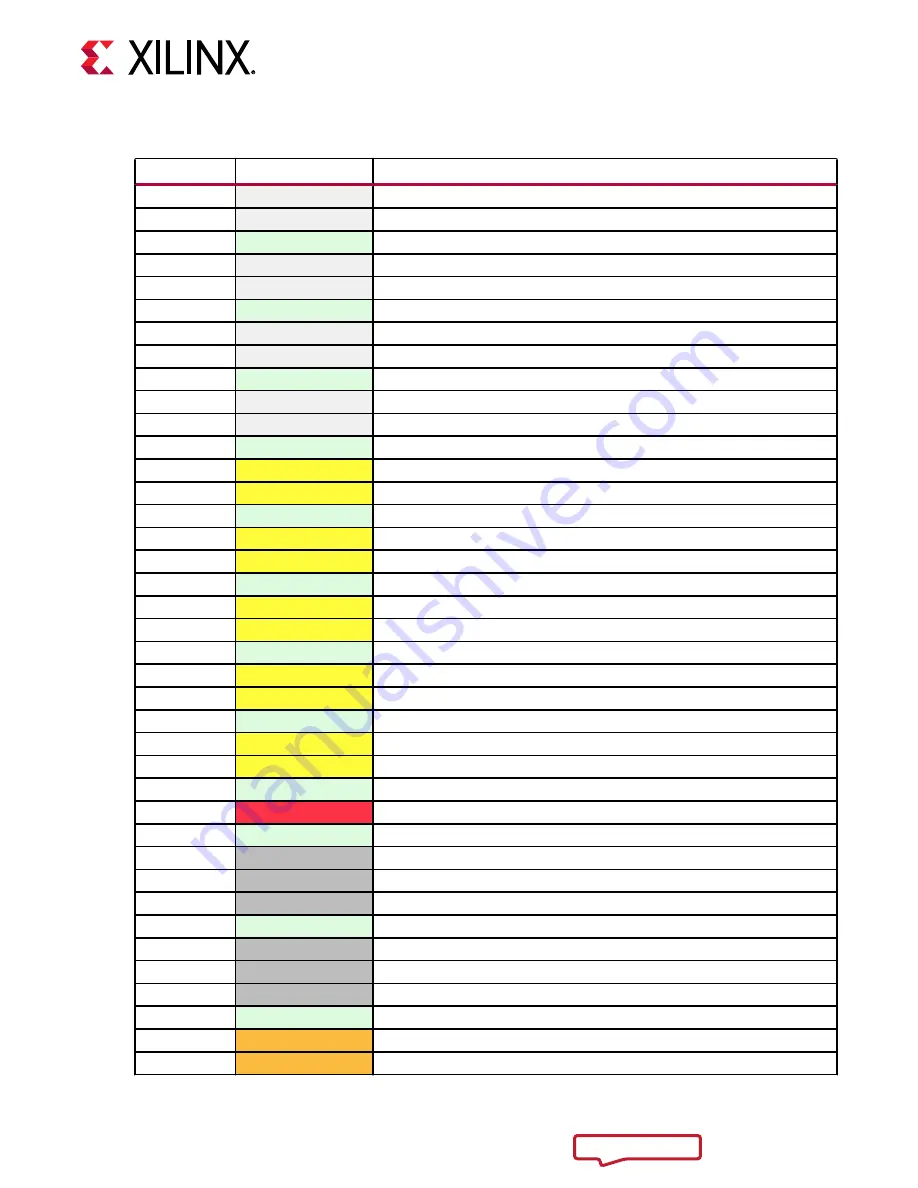
Table 6: SOM240_2 Signal Pins (cont'd)
Pin Number
Signal Name
Signal Description
B15
HPB07_P
HPIO on bank 65
B16
HPB07_N
HPIO on bank 65
B17
GND
Ground
B18
HPB05_CC_P
HPIO clock-capable pin on bank 65
B19
HPB05_CC_N
HPIO clock-capable pin on bank 65
B20
GND
Ground
B21
HPB11_P
HPIO on bank 65
B22
HPB11_N
HPIO on bank 65
B23
GND
Ground
B24
HPB03_P
HPIO on bank 65
B25
HPB03_N
HPIO on bank 65
B26
GND
Ground
B27
HPC06_P
HPIO on bank 64
B28
HPC06_N
HPIO on bank 64
B29
GND
Ground
B30
HPC13_P
HPIO on bank 64
B31
HPC13_N
HPIO on bank 64
B32
GND
Ground
B33
HPC16_P
HPIO on bank 64
B34
HPC16_N
HPIO on bank 64
B35
GND
Ground
B36
HPC07_P
HPIO on bank 64
B37
HPC07_N
HPIO on bank 64
B38
GND
Ground
B39
HPC18_P
HPIO on bank 64
B40
HPC18_N
HPIO on bank 64
B41
GND
Ground
B42
VCCO_HPB
HPB I/O voltage rail, 1.0V to 1.8V
B43
GND
Ground
B44
HDB12
HDIO on bank 43
B45
HDB13
HDIO on bank 43
B46
HDB14
HDIO on bank 43
B47
GND
Ground
B48
HDB15
HDIO on bank 43
B49
HDB16_CC
HDIO clock-capable pin on bank 43
B50
HDB17
HDIO on bank 43
B51
GND
Ground
B52
HDC12
HDIO on bank 44
B53
HDC13
HDIO on bank 44
Chapter 2: Electrical Design Considerations
UG1091 (v1.0) April 20, 2021
Carrier Card Design for Kria SOM
21


