Error Codes and Messages
2 - 41
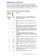
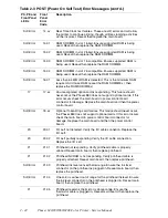
POST (Power On Self Test)
When these tests begin the front panel has been initialized. In most cases, if an error
occurs, a text message is displayed on the front panel along with an LED blink code
flashing on all three LEDs (front panel LED, PS LED and PE LED). The LED blink codes
are setup similarily to the 840 and 850: Short Blink = 1, Long Blink = 5. Both rear panel
LED’s and the front panel LED all blink together for the 860 POST messages.
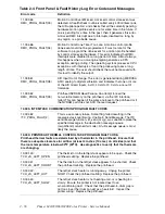
Table 2-3 POST (Power On Self Test) Error Messages
PS, PE and
Front Panel
LEDs
Front
Panel
Error
Code
Description
Rear panel
LEDs cycle
back and
forth
RAM
ERROR
Neither RAM socket has a supported RAM SODIMM installed.
Ensure that supported RAM is being used. Reseat and then
replace the RAM SODIMM.
2
2.01
Failure to read the chip ID’s. Reseat and then replace the main
board.
2
2.02
Failure testing timer values. Reseat and then replace the main
board.
4
4.01
Neither I/O Right or the front panel are detected. Verify the IIC
cable connections then replace the I/O Right. NO FRONT PANEL
MESSAGE WILL BE DISPLAYED FOR THIS ERROR.
5
5.01
The front panel is not detected. Verify the IIC cable connections
and the state of the front panel sensor. Replace the front panel. NO
FRONT PANEL MESSAGE WILL BE DISPLAYED FOR THIS
ERROR.
6
6.01
The duplex sensor is detected but the front panel is not
responding. Verify the IIC cable connections. Replace the front
panel. NO FRONT PANEL MESSAGE WILL BE DISPLAYED FOR
THIS ERROR.
7
7.01
Front panel is detected but the I/O Right is not responding. Replace
I/O Right.
10
10.01
EEPROM read failure. Reseat then replace the Printer ID chip.
10
10.02
EEPROM write failure. Reseat then replace the Printe ID chip.
10
10.03
EEPROM re-read failure. Reseat then replace the Printer ID chip.
10
10.04
EEPROM write/read mismatch. Reseat then replace the main
board.
11
11.01
Ethernet port chip failure. Reseat then replace the main board.
11
11.02
Ethernet port ID error. Reseat then replace the main board.
12
12.xx
CPU Interrupt test failure or unexpected interrupt request. Reseat
then replace the main board.
13
13.01
USB test failure. Reseat then replace main board.
Summary of Contents for Phaser 840
Page 2: ......
Page 12: ...vi Phaser 840 850 860 8200 Color Printer Service Manual ...
Page 52: ...1 36 Phaser 840 850 860 8200 Color Printer Service Manual ...
Page 88: ...2 72 Phaser 840 850 860 8200 Color Printer Service Manual Blank Page ...
Page 134: ...3 118 Phaser 840 850 860 8200 Color Printer Service Manual ...
Page 174: ...4 158 Phaser 840 850 860 8200 Color Printer Service Manual ...
Page 188: ......
Page 250: ...8 234 Phaser 840 850 860 8200 Color Printer Service Manual ...
Page 286: ...270 Phaser 840 850 860 8200 Color Printer Service Manual ...
Page 287: ...071 0723 00 ...

