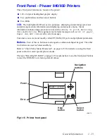

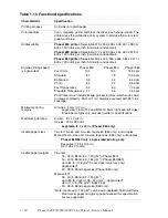


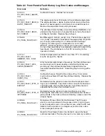
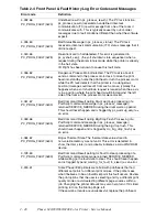
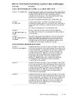
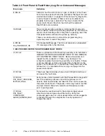


Error Codes and Messages
2 - 37
Error Codes and
Messages
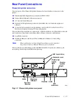
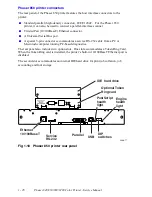
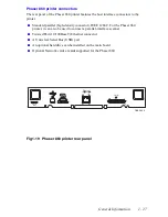
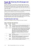
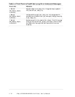
Phaser 840/850 Rear Panel PS and PE LED
Codes
The rear panel LEDs are located on each side of the rear panel DIP switches.
The left LED
represents the operation of the PostScript firmware. The right LED represents operation
of the main board’s print engine firmware.
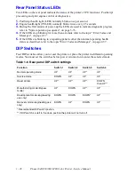
During the POST tests, the two LEDs toggle
back and forth for each successful pass through each SDRAM test. A failure in the power
on self tests is indicated by the left LED (the PS LED) flashing in a specific pattern of long
and/or short flashes and repeated indefinitely. A long flash represents a 5, while a short
flash is a 1. For example, a long flash followed by 4 short flashes is 5 + 4 = 9. If the left
LED repeatedly flashes in the same sequence, then the PostScript processor has
encountered an error and is looping.
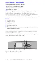
For the Phaser 850 printer
, when a fatal error occurs, the front panel Error LED flashes
the same pattern as the PS LED. The possible LED-encoded error codes are listed in the
following table. Other failures are indicated by the failure being printed on the Startup
Page.
After successful power-up, the left LED flashes at a regular “heartbeat” rate. The front
panel
Power
light turns on, the
Error
light flashes, and the LCD is cleared.
When troubleshooting Rear Panel LED Codes try reseating the affected components first.
If the problem continues then replace the affected components.
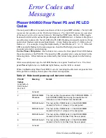
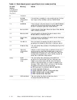
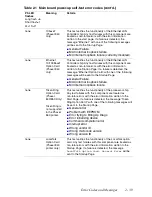
Table 2-1 Main board power-up self-test error codes
PS LED
flashes
Long flash =5
Short flash=1
2L+1S=11
Meaning
Details
1
not used
2
SDRAM SIMM
Presence
This test verifies the presence of both SDRAM SIMMs. If
both SDRAM SIMMs are missing the resultant error
indication is 2 short flashes from the left LED.
3
SDRAM bank 0
This test verifies DRAM bank 0 in the DRAM DIMM
located in Position 1 (closest to the rear panel).
4
SDRAM bank 1
This test verifies DRAM bank 1 in the DRAM DIMM
located in Position 1 (closest to the rear panel).
5
SDRAM bank 2
This test verifies DRAM bank 0 in the DRAM DIMM
located in Position 2 (farthest from the rear panel).
6
SDRAM bank 3
This test verifies DRAM bank 1 in the DRAM DIMM
located in Position 2 (farthest from the rear panel).
7
not used
Summary of Contents for Phaser 840
Page 2: ......
Page 12: ...vi Phaser 840 850 860 8200 Color Printer Service Manual ...
Page 52: ...1 36 Phaser 840 850 860 8200 Color Printer Service Manual ...
Page 88: ...2 72 Phaser 840 850 860 8200 Color Printer Service Manual Blank Page ...
Page 134: ...3 118 Phaser 840 850 860 8200 Color Printer Service Manual ...
Page 174: ...4 158 Phaser 840 850 860 8200 Color Printer Service Manual ...
Page 188: ......
Page 250: ...8 234 Phaser 840 850 860 8200 Color Printer Service Manual ...
Page 286: ...270 Phaser 840 850 860 8200 Color Printer Service Manual ...
Page 287: ...071 0723 00 ...