background image

102

Connection Configuration

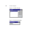
Figure 13-1

Dial-Up Configuration Wizard 1

To use the first dialog box:

1. Enter a name for your dial-up connection (a maximum of 20 characters).

2. Click on Next.

Summary of Contents for Winterm 3200LE

Page 1: ...Winterm 3000 Series Windows based Terminal Administrators Guide ...

Page 2: ......

Page 3: ...Winterm 3000 Series Windows based Terminal Administrators Guide 883628 02 Rev A May 2000 Wyse Technology Inc 3471 North First Street San Jose CA 95134 1803 ...

Page 4: ......

Page 5: ...ed trademark and MetaFrame is a trademark of Citrix Systems Inc Microsoft Windows Windows CE Windows NT and Windows Terminal Server are registered trademarks of Microsoft Corporation All other products are trademarks and or registered trademarks of their respective companies The Energy Star emblem does not represent endorsement of any product or service Specifications subject to change without not...

Page 6: ...bility pricing and ordering information in the United States and Canada call 1 800 GET WYSE 1 800 438 9973 In all other countries contact your sales representative Wyse Technology Inc 3471 North First Street San Jose CA 95134 1803 U S A ...

Page 7: ...n of the unused product s for a refund Software License The SOFTWARE is protected by copyright laws and international copyright treaties as well as other intellectual property laws and treaties The SOFTWARE is licensed not sold 1 Grant of License SOFTWARE includes software already installed on the SYSTEM SYSTEM SOFTWARE and if included in the SYSTEM package software contained on the CD ROM disk an...

Page 8: ...RER has not included a back up copy of the SYSTEM SOFTWARE with the SYSTEM you may make a single back up copy of the SYSTEM SOFTWARE You may use the back up copy solely for archival purposes 2 Description of Other Rights and Limitations Speech Handwriting Recognition If the SYSTEM SOFTWARE includes speech and or handwriting recognition component s you should understand that speech and handwriting ...

Page 9: ...ay terminate this EULA if you fail to comply with the terms and conditions of this EULA In such event you must destroy all copies of the SOFTWARE and all of its component parts 3 Upgrades If the SYSTEM SOFTWARE and this EULA are provided separate from the SYSTEM by MANUFACTURER and the SYSTEM SOFTWARE is on a ROM chip CD ROM disk s or floppy disk s and labeled For ROM Upgrade Purposes Only ROM Upg...

Page 10: ...eled North America Only Version above on the Product Identification Card or on the SOFTWARE packaging or other written materials then the following applies The SOFTWARE is intended for distribution only in the United States its territories and possessions including Puerto Rico Guam and U S Virgin Islands and Canada Export of the SOFTWARE from the United States is regulated under EI controls of the...

Page 11: ...ECTION ABOVE THE SOFTWARE IS PROVIDED TO THE END USER AS IS WITHOUT WARRANTY OF ANY KIND EITHER EXPRESSED OR IMPLIED INCLUDING BUT NOT LIMITED TO WARRANTIES OF NON INFRINGEMENT MERCHANTABILITY AND OR FITNESS FOR A PARTICULAR PURPOSE THE ENTIRE RISK OF THE QUALITY AND PERFORMANCE OF THE SOFTWARE IS WITH YOU No Liability for Consequential Damages MANUFACTURER OR MANUFACTURER S SUPPLIERS INCLUDING MS...

Page 12: ...mentation are provided with RESTRICTED RIGHTS Use duplication or disclosure by the Government is subject to restrictions as set forth in subparagraph c 1 ii of the Rights in Technical Data and Computer Software clause at DFARS 252 227 7013 or subparagraphs c 1 and 2 of the Commercial Computer Software Restricted Rights at 48 CFR 52 227 19 as applicable MANUFACTURER is Microsoft Corporation One Mic...

Page 13: ... the equipment off and on the user is encouraged to try to correct the interference by one or more of the following measures Reorient or relocate the receiving antenna Increase the separation between the equipment and the receiver Connect the equipment into an outlet on a circuit different from that to which the receiver is connected Consult the dealer or an experienced radio TV technician for hel...

Page 14: ...imits for radio noise emissions from digital apparatus set out in the Radio Interference Regulations of the Canadian Department of Communications Le présent appareil numérique n émet pas de bruits radioélectriques dépassant les limites applicables aux appareils numériques de la classe B prescrites dans le Réglement sur le brouillage radioélectrique édicté par le Ministère des Communications du Can...

Page 15: ...ction with the Wyse Terminal You may transfer ownership of the Terminal and equipment including the right to use the Software to another party so long as that party agrees to accept these terms and conditions YOU MAY NOT USE COPY MODIFY TRANSLATE OR TRANSFER THE SOFTWARE OR MODIFICATION THEREOF IN WHOLE OR IN PART EXCEPT AS EXPRESSLY PROVIDED FOR IN THIS LICENSE YOU MAY NOT DECOMPILE REVERSE ENGIN...

Page 16: ...E THE ONLY APPLICABLE TERMS OF AGREEMENT BETWEEN US COVERING SOFTWARE AND THAT THEY SUPERSEDE ANY OTHER COMMUNICATIONS ORAL OR WRITTEN BETWEEN US RELATING TO THE SOFTWARE Export Restrictions You agree You will not export or transmit the Software to any country to which export is restricted by applicable US law or regulation without the written approval of the appropriate US Government organization...

Page 17: ...n 1 Model 3200LE Terminal Installation Locating the Terminal 3 Connecting the Terminal 3 Turning On the Terminal 5 2 Model 3320SE Terminal Installation Locating the Terminal 7 Connecting the Terminal 7 Mounting the Terminal 10 Freestanding Desktop Mounting 10 Wall Mounting 11 Optional Cable Retaining Clip and Shroud Installation 13 Turning On the Terminal 16 ...

Page 18: ...Clip and Shroud Installation 31 Turning On the Terminal 34 5 Model 3720SE Terminal Installation Locating the Terminal 35 Connecting the Terminal 35 Turning On the Terminal 37 Display Adjustments 38 Advanced User Interface 6 Initial Terminal Setup Using the Setup Wizard 45 7 Changing Terminal Properties Using the Terminal Properties Dialog Box 61 Resetting to Factory Defaults 62 Terminal Settings C...

Page 19: ...Wizard 91 Network Connections 92 Dial In Connection 98 13 Dial Up Connections Using the Dial Up Configuration Wizard 101 14 Dial Up Dialing Properties and Configuration Using the Dialing Properties Dialog Box 105 Using the Device Properties Dialog Box 108 Port Settings 109 Call Options 110 15 Dial Up TCP IP Settings and Security Using the TCP IP Settings Dialog Box 111 Using the Security Settings ...

Page 20: ...g the Title Properties Sheet 148 Using the Firewall Settings Properties Sheet 149 21 Editing RDP Dial Up and Terminal Emulation Connections Dial Up and Terminal Emulation Connections 151 RDP Connections 151 Using the Edit Connection Dialog Box 152 Using the Net Connections Properties Sheet 153 Using the Application Properties Sheet 154 External Devices 22 Devices Properties Devices Properties Shee...

Page 21: ...ing the RACORE Token Ring Adapter Settings Dialog Box 189 28 PC Card Adapters for Wireless Networks Using the WaveLAN IEEE Settings Dialog Box 191 Basic Properties Sheet 191 Advanced Properties 193 Power Management 195 Encryption 196 29 Volume Properties Using the Volume Properties Dialog Box 197 Firmware Upgrades 30 Cable Firmware Upgrades Setup 201 Parallel Flash Download Procedure 202 Manual Do...

Page 22: ... the Security Properties Sheet 227 35 Terminal Accounts Guest Accounts 233 User Accounts 234 Administrator Accounts 234 Using Terminal Accounts 234 36 Creating Terminal Accounts Using the Add User Account Dialog Box 235 37 Modifying and Deleting Terminal Accounts Using the Modify User Account Dialog Box 241 Deleting Terminal Accounts 245 38 Terminal Login Logging Into the Terminal 247 Autologin an...

Page 23: ... Specifications 41 How to 42 Terminal Port Pin Assignments 43 Terminal Connector Pin Assignments 44 Null Modem Cable Pin Assignments 45 Modem AT Commands 46 Noise Suppressor Installation Appendix A SNMP Remote Configuration Chart Glossary Index ...

Page 24: ...erminal Back Panel Connectors 36 5 2 3720SE Terminal Front Panel 38 5 3 3720SE OSD On Screen Display Menu 39 5 4 3720SE Recall Mode 41 6 1 Welcome Dialog Box 46 6 2 Countdown Dialog Box 47 6 3 IP Address Dialog Box 48 6 4 Specify an IP Address Dialog Box 49 6 5 Optional Information Dialog Box 50 6 6 Desktop Area and Refresh Frequency Dialog Box 51 6 7 Local Printer Setup Dialog Box 53 6 8 Select P...

Page 25: ... Dialog Box 108 14 3 Call Options Properties Sheet 110 15 1 TCP IP Settings Dialog Box 112 15 2 Security Settings Dialog Box 113 16 1 Script Name Dialog Box 116 16 2 New Script Name Dialog Box 116 16 3 RAS Script Dialog Box 117 16 4 Edit Script Line Dialog Box 118 17 1 WTS Connection Wizard 1 120 17 2 WTS Connection Wizard 2 121 17 3 WTS Connection Wizard 3 122 17 4 WTS Connection Wizard 4 123 18 ...

Page 26: ... IEEE Settings Dialog Box 192 28 2 Advanced Properties Sheet 193 28 3 Power Management Properties Sheet 195 28 4 Encryption Properties Sheet 196 29 1 Volume Properties Dialog Box 197 30 1 Download Utility Dialog Box 203 30 2 Parallel Download Cable Connectors 205 31 1 Upgrade Properties Sheet 208 31 2 Firmware Upgrade Dialog Box 1 211 31 3 Firmware Upgrade Dialog Box 2 211 32 1 SNMP Network Admini...

Page 27: ...ialog Box 89 14 1 Dialing Properties Dialog Box 107 14 2 Port Settings Properties Sheet 109 14 3 Call Options Properties Sheet 110 15 1 TCP IP Settings Dialog Box 112 15 2 Security Settings Dialog Box 114 16 1 RAS Script Dialog Box 117 18 1 Terminal Emulation and Terminal Type 127 19 1 TCP IP Telnet Configuration 134 19 2 Modem Settings Dialog Box 137 19 3 Configuration of Serial Cable on Com1 Dia...

Page 28: ...8 30 1 Parallel Download Cable Pinouts 204 31 1 Upgrade Properties Sheet 209 32 1 SNMP Network Administration Dialog Box 215 33 1 Change DHCP Option IDs Dialog Box 221 34 1 Security Properties Sheet 229 36 1 Add User Account Dialog Box 237 37 1 Modify User Account Dialog Box 243 40 1 Specifications for the 3200LE Terminal 255 40 2 Specifications for the 3320SE and 3350SE Terminals 257 40 3 Specifi...

Page 29: ...s the Models 3200LE 3320SE 3350SE 3360SE and 3720SE terminals Guide Overview The administrators guide consists of the following chapters Terminal Installation Advanced User Interface Connection Configuration External Devices Firmware Upgrades Client Security Getting Help This guide contains information about Terminal specifications and installations The WBT user interface Physical and network conn...

Page 30: ...ok title or emphasis Bold Screen display keycaps and user input Note This convention indicates a note A note adds information Caution This convention indicates a caution A caution indicates actions that may cause damage to equipment erase files or destroy data Keystroke sequences such as Ctrl Alt Del Instructions about invoking a menu such as Network SNMP Network Location ...

Page 31: ...hanges and quit a dialog box or properties sheet Cancel Found in dialog boxes and on properties sheets Click on this command button at any time to quit a dialog box or properties sheet without saving changes Apply Found in dialog boxes and on properties sheets Click on this command button to save changes without quitting a dialog box or properties sheet Next or Accept Found in wizards Click on the...

Page 32: ...xxx ...

Page 33: ...rminal Installation 1 Model 3200LE Terminal Installation 2 Model 3320SE Terminal Installation 3 Model 3350SE Terminal Installation 4 Model 3360SE Terminal Installation 5 Model 3720SE Terminal Installation ...

Page 34: ...2 ...

Page 35: ...For more information call 1 800 800 WYSE 9973 Note A keyboard and AC power cord are supplied with U S models only Locating the Terminal Position the terminal on a clean horizontal surface that is free from vibration and out of direct sunlight Refer to Windows based Terminal Specifications for environmental specifications Connecting the Terminal Make all connections to the back panel before connect...

Page 36: ...le port Digi device Table 1 1 3200LE Terminal Back Panel Connectors and Indicators Connector Description LED Indicators The 10 or 100 indicator lights to indicate the network type to which the terminal is connected 10 100 Base T The Act indicator flashes when there is activity on the line Network LAN connector 10 100Base T Headphone Audio output jack for headphones Microphone Audio input jack for ...

Page 37: ...ered up and operating when the power supply is connected to AC power To toggle the display off or on press and release the power management button If the button is continuously depressed for 3 5 seconds the unit will perform a hard boot See Figure 1 2 for the location of the power management button Figure 1 2 3200LE Terminal Power Management Button The logo will appear on the screen followed by Th...

Page 38: ...6 Terminal Installation ...

Page 39: ... keyboard and AC power cord are supplied with U S models only Locating the Terminal Position the terminal on a clean horizontal surface that is free from vibration and out of direct sunlight Refer to Windows based Terminal Specifications for environmental specifications Connecting the Terminal Make all connections to the back panel before connecting the terminal to power An optional shroud and cab...

Page 40: ...8 Terminal Installation Figure 2 1 3320SE Terminal Back Panel Connectors Mouse Keyboard COM 2 COM 1 Power Parallel Option Network Headphone Microphone Video ...

Page 41: ...efore connecting the cables Table 2 1 3320SE Terminal Back Panel Connectors Connector Description Network LAN connector 10 100Base T Com1 Serial port 1 Can be connected to an external modem Can be used for a direct connection to a local server Can be connected to a serial printer Com2 Serial port 2 Can be connected to an external modem Can be used for a direct connection to a local server Can be c...

Page 42: ... to the socket 6 Plug the AC cord into the power supply then into an AC outlet 7 After the cables are connected install the terminal in its planned location either on a desktop or optionally mounted to a wall Mounting the Terminal The terminal can be freestanding or attached to a wall an optional wall mount kit is required Instructions for mounting your terminal are provided in the following parag...

Page 43: ... be mounted on a wall using the optional wall mounting bracket The following figure shows the wall mount configuration Note It is best to connect the cables before mounting the terminal on a wall However cables can be attached at any convenient time as long as power is disconnected ...

Page 44: ...re has the bracket mounted to the terminal first and then the complete assembly is placed on wall anchor screws If there is any risk that the terminal could be bumped from its mounting the bracket should be securely anchored to the wall first and then the terminal housing mounted to the bracket Wall Anchors Wall Shroud Mounting Clips Screws 2 Wall Mounting Bracket ...

Page 45: ...e back of the terminal housing 6 Slip the lower tabs of the mounting bracket under the two screws loosened in step 4 The tabs should go between the screw heads and the mounting clips 7 Tighten the screws to hold the bracket firmly in place 8 Hang the terminal assembly on the wall anchor mounting screws 9 Install the cable retaining loop and shroud using the procedure that follows Optional Cable Re...

Page 46: ...rt and place it over the cables 5 Place the slots in the lower end split end of the shroud under the lower shroud mounting clip as shown in the following figure 6 Rotate the upper end of the shroud until the top slot goes over and engages the upper mounting clip as shown in the following figure Retainer Catches Cable Retaining Loop ...

Page 47: ...15 Figure 2 5 3320SE Optional Shroud Installation Cable Retaining Loop Upper Shroud Mounting Clip Lower Shroud Mounting Clip Slot Slots Shroud ...

Page 48: ...igure for the location of the power management button Figure 2 6 3320SE Power Management Button The logo will appear on the screen followed by The Setup Wizard if it is the first time that you have turned on your terminal The Winterm Connection Manager dialog box if the Setup Wizard has been completed If desired adjust the display s geometry and intensities to your preferences Adjustments to the d...

Page 49: ...available For more information call 1 800 800 WYSE 9973 Note A keyboard and AC power cord are supplied with U S models only Locating the Terminal Position the terminal on a clean horizontal surface that is free from vibration and out of direct sunlight Refer to Windows based Terminal Specifications for environmental specifications Connecting the Terminal Make all connections to the back panel befo...

Page 50: ...18 Terminal Installation Figure 3 1 3350SE Terminal Back Panel Connectors COM 2 Power Option Keyboard Microphone COM 1 Parallel Video Network Headphone USB Mouse ...

Page 51: ... of the operating system programs from the host computer Can be connected to a serial printer Com2 Serial port 2 Can be connected to an external modem Can be used for a direct connection to a local server Can be connected to a serial printer Parallel Port Local printer output Video Monitor interface Keyboard Keyboard interface Mouse Mouse interface Power Power module output cable interface Card Bu...

Page 52: ...ter to the parallel port and or connect a modem server serial cable to the serial ports as appropriate 5 Connect the power supply output cable to the Power connector Caution Do not force a connector into its socket If any undue resistance is encountered ensure that the connector is oriented correctly to the socket 6 Plug the AC cord into the power supply then into an AC outlet 7 After the cables a...

Page 53: ...ponents could occur if the mounting bolts protrude past the tops of the guide holes Follow these instructions for permanent desktop mounting 1 Make a template of the desktop mounting holes using the bottom of the terminal and use it to mark the desktop area where you want to mount the terminal 2 Drill holes for the mounting bolts through the desktop mounting surface at the marked locations 3 Place...

Page 54: ...al Wall Mount Configuration Follow these instructions to mount the terminal on a wall Note The following procedure has the bracket mounted to the terminal first and then the complete assembly is placed on wall anchor screws Mounting Bracket Tabs Bolts ...

Page 55: ...to the side of the terminal 6 Insert the mounting bolts up through the holes in the bottom of the mounting bracket and into the threaded holes in the terminal base plate 7 Tighten the mounting bolts to hold the bracket firmly in place 8 Hang the terminal assembly on the wall anchor mounting screws 9 Install the cable retaining loop and shroud using the procedure below Shroud Attachment A plastic s...

Page 56: ...SE Power Management Button The logo will appear on the screen followed by The Setup Wizard if it is the first time that you have powered up your terminal The Winterm Connection Manager dialog box if the Setup Wizard has been completed If desired adjust the display s geometry and intensities to your preferences Adjustments to the display can be made at any time whether or not the terminal is connec...

Page 57: ...A keyboard and AC power cord are supplied with U S models only Locating the Terminal Position the terminal on a clean horizontal surface that is free from vibration and out of direct sunlight Refer to Windows based Terminal Specifications for environmental specifications Connecting the Terminal Make all connections to the back panel before connecting the terminal to power An optional shroud and ca...

Page 58: ...26 Terminal Installation Figure 4 1 3360SE Terminal Back Panel Connectors COM 1 COM 2 Option Keyboard Microphone Headphone Video Parallel Mouse Power Network USB ...

Page 59: ...es or install the mounting bracket wall anchors before connecting the cables Table 4 1 3360SE Terminal Back Panel Connectors Connector Description Network Connector LAN connector 10 100Base T Com1 Serial port 1 Can be connected to External modem Local server Serial printer Com2 Serial port 2 Can be conected to External modem Local server Serial printer Touch screen monitor Parallel Port Local prin...

Page 60: ... AC cord into the power supply then into an AC outlet 7 After the cables are connected install the terminal in its planned location either on a desktop or mounted to a wall see the next section Mounting the Terminal Mounting the Terminal The terminal can be freestanding or attached to a wall an optional wall mount kit is required Instructions for mounting your terminal are provided in the followin...

Page 61: ... be mounted on a wall using the optional wall mounting bracket The following figure shows the wall mount configuration Note It is best to connect the cables before mounting the terminal on a wall However cables can be attached at any convenient time as long as power is disconnected ...

Page 62: ...re has the bracket mounted to the terminal first and then the complete assembly is placed on wall anchor screws If there is any risk that the terminal could be bumped from its mounting the bracket should be securely anchored to the wall first and then the terminal housing mounted to the bracket Wall Anchors Wall Shroud Mounting Clips Screws 2 Wall Mounting Bracket ...

Page 63: ...e back of the terminal housing 6 Slip the lower tabs of the mounting bracket under the two screws loosened in step 4 The tabs should go between the screw heads and the mounting clips 7 Tighten the screws to hold the bracket firmly in place 8 Hang the terminal assembly on the wall anchor mounting screws 9 Install the cable retaining loop and shroud using the procedure that follows Optional Cable Re...

Page 64: ...rt and place it over the cables 5 Place the slots in the lower end split end of the shroud under the lower shroud mounting clip as shown in the following figure 6 Rotate the upper end of the shroud until the top slot goes over and engages the upper mounting clip as shown in the following figure Retainer Catches Cable Retaining Loop ...

Page 65: ...33 Figure 4 5 3360SE Optional Shroud Installation Cable Retaining Loop Upper Shroud Mounting Clip Lower Shroud Mounting Clip Slot Slots Shroud ...

Page 66: ...form a hard boot See the following figure for the location of the power management button Figure 4 6 3360SE Power Management Button The logo will appear on the screen followed by The Setup Wizard if it is the first time that you have turned on your terminal The Winterm Connection Manager dialog box if the Setup Wizard has been completed If desired adjust the display s geometry and intensities to y...

Page 67: ...lean horizontal surface that is free from vibration and out of direct sunlight Allow 75 mm 3 in of clearance on all sides of the terminal for air circulation and movement of the tilt swivel mechanism Refer to Windows based Terminal Specifications for environmental specifications Connecting the Terminal Before powering up the terminal connect it to all of its peripheral devices Figure 5 1 shows the...

Page 68: ...cted to the external modem or used for direct connection to a local server Can be used for the emergency download of the operating system programs from the host computer Can be connected to a serial printer Com2 Serial port 2 Can be connected to an external modem Can be used for a direct connection to a local server Can be connected to a serial printer Can be connected to a monitor that supports t...

Page 69: ...perating when the power supply is connected to AC power To toggle the display off or on press and release the power management button Note If the button is continuously depressed for 3 5 seconds the unit will perform a hard boot See the figure on the following page for the location of the power management button Parallel Port Local printer output Keyboard Keyboard interface Mouse Mouse interface P...

Page 70: ... not the terminal is connected to a server If your terminal is installed with an optional touchscreen calibrate it now Refer to Input Configuration for the procedure Display Adjustments The following sections explain how to adjust the screen s brightness contrast horizontal and vertical size and phase pincushion and trapezoid The terminal uses an OSD on screen display adjustment feature The OSD is...

Page 71: ... the adjustment you want to make see the following table OSD Alignment for settings 3 Press the ADJUST plus or minus buttons to make your adjustment 4 Press MENU to save your adjustments and close the OSD SELECT Brightness Press the plus and minus buttons on the terminal s front panel to increase or decrease the display s brightness ADJUST Contrast Press the plus and minus buttons on the terminal ...

Page 72: ...re both sides of the display sag inward toward the center or bow outward from it TRAPEZOID TRAPEZOID adjusts the screen s right and left hand sides so they are parallel ROTATE ROTATE corrects the screen s rotation Use this function if the display tilts left or right RECALL MODE Select this item to reset the display to the factory preset color temperatures also see the following figure RECALL MODE ...

Page 73: ...41 Figure 5 4 3720SE Recall Mode R G B 9300 K 1 2 3 R G B USER 1 1 2 3 RECALL 9300K ...

Page 74: ...42 Terminal Installation ...

Page 75: ...Advanced User Interface 6 Initial Terminal Setup 7 Changing Terminal Properties 8 Network Configuration 9 Additional Terminal Applications 10 ICA Client Settings ...

Page 76: ...44 ...

Page 77: ...sheet Using the Setup Wizard The Setup Wizard lets you set terminal network configuration and terminal display parameters Several dialog boxes display in succession during the process Each dialog box is self explanatory Some dialog boxes are informational and require no user input Other dialog boxes prompt you for network printer and display information See Figure 6 1 to view the first dialog box ...

Page 78: ...ced User Interface Figure 6 1 Welcome Dialog Box The Welcome dialog box is mostly informational providing product information Click on Next to continue with the installation by opening the Countdown dialog box ...

Page 79: ...2 Countdown Dialog Box The one function the Countdown dialog box carries is a countdown Click on Next during the countdown to zero to continue with the wizard Let the count go to zero to auto configure the terminal ...

Page 80: ...P information supplied by DHCP and click on Next the Optional Information dialog box will display skipping the Specify an IP Address dialog box Note For first time setup or a reset in the event that the terminal is not automatically assigned a DHCP address while initializing No I will enter static IP information is the default Some or all of the IP information required for this terminal could not ...

Page 81: ...49 Figure 6 4 Specify an IP Address Dialog Box Enter the addressing information requested in the fields provided By default the fields are blank Click on Next to go to the next step ...

Page 82: ...o enable name resolution Enable DNS Enables Domain Name Services Enable WINS Windows Internet Naming Services Enter the information in the text fields that are activated By default the check boxes are unselected and the text fields are inactivated Click on Next to go to the next step ...

Page 83: ...Frequency dialog box Table 6 1 Desktop Area and Refresh Frequency Dialog Box Function Description Desktop Area and Refresh Frequency Select from the scroll list to set your resolution Other settings are Best Available Using DDC Supported in all terminals 640 x 480 60Hz Supported in all terminals 640 x 480 75Hz Supported in all terminals ...

Page 84: ...4 x 768 75Hz Supported in all terminals 1024 x 768 85 Hz Supported in all terminals 1280 x 1024 60 Hz Supported in the 3350SE 3360SE and 3720SE terminals Test Click on this command button to test the selection you made in Desktop Area and Refresh Frequency The following dialog box displays After making the selectiion click on Next to go to the next step Table 6 1 Desktop Area and Refresh Frequency...

Page 85: ...elect Yes and the dialog boxes that follow will ask for printer information Note This local printer setup applies only to RDP and terminal emulation connections See Local Printers for further information If you select No the default you will skip the remaining printer dialog boxes and the Finish dialog box will display Make your selection and click on Next ...

Page 86: ...54 Advanced User Interface Figure 6 8 Select Printer Port Dialog Box In the Select Printer Port dialog box select the port to which the printer is connected and click on Next to go to the next step ...

Page 87: ...55 Figure 6 9 Select Printer Model Dialog Box In the Select the Printer Model dialog box select the printer model from the list and click on Next to go to the next step ...

Page 88: ...56 Advanced User Interface Figure 6 10 Printer Name Dialog Box In the Name Your Printer dialog box enter a name by which to refer to your printer and click on Next to go to the next step ...

Page 89: ...t Printer Dialog Box In the Set Default Printer dialog box select whether or not you want your Windows based programs to use this printer as the default printer Yes is the default selection Click on Next to go to the next step ...

Page 90: ... If you have another printer connected to a different port on your terminal select Yes in the Configure another printer dialog box Click on Next to go to the next step If you selected Yes the printer setup process will repeat If you selected No the Finish dialog box will open ...

Page 91: ...nish Dialog Box The Finish dialog box is informational Click on the Finish command button to apply your selections and quit the Setup Wizard After the Setup Wizard closes the Terminal Settings Change dialog box displays ...

Page 92: ... you click on Restart the terminal will go through the boot process and restart in the normal operating mode If you want to want to change any of the selections after you restart press F2 to open the Terminal Properties dialog box see Changing Terminal Properties for instructions ...

Page 93: ... total of 10 properties sheets that can be invoked by clicking on their individual tabs The following 6 sheets are used to change terminal properties Network discussed in Network Configuration Upgrade discussed in FTP Pull Firmware Upgrades Security discussed in Security Properties Apps discussed in Additional Applications Devices discussed in Dial Up Connections Printers discussed in Local Printe...

Page 94: ...amount of RAM that is available depends on the model of terminal in use Resetting to Factory Defaults There is one function on the General properties sheet Reset the Terminal to Factory Default Property Settings Use this function to reset the terminal to factory default settings ...

Page 95: ...on about this dialog box 4 Click on Restart in the System Settings Change dialog box to restart the terminal with factory defaults in effect Figure 7 2 System Settings Change Dialog Box Terminal Settings Change Dialog Box When you change terminal properties using the Setup Wizard or the Terminal Properties dialog box you will click on either the Finish or OK command button to save your new setting...

Page 96: ...ntains the Restart command button The terminal must be restarted in order for your new settings to take effect Click on Restart to restart the terminal The Winterm Connection Manager displays See Connections Management for detailed information about configuring and making terminal connections ...

Page 97: ...perties sheet lets you configure your network See Figure 8 1 to view this properties sheet Using the Network Properties Sheet To invoke this properties sheet 1 Press F2 to invoke the Terminal Properties dialog box 2 Click on the Network tab ...

Page 98: ...66 Advanced User Interface Figure 8 1 Network Properties Sheet The following table discusses the functions of the Network properties sheet ...

Page 99: ...a static IP address in this field Subnet Mask Enter the subnet mask of the IP address Gateway Enter the gateway of the IP address Terminal Name Enter a name of your choice for the terminal Use this scroll list to select a network communication speed The choices are in Mb s Auto Detect 10 Mbs Half Duplex 10 Mbs Full Duplex 100 Mbs Half Duplex 100 Mbs Full Duplex Note If you do not know your network...

Page 100: ... deactivated Enable DNS Use this group box to set domain primary and secondary IP addresses for DNS Enable the function by clicking to check Enable DNS The default for the function is disabled Enable WINS Use this group box to set the primary and secondary IP addresses of a WINS server Enable the function by clicking to check Enable WINS The default for the function is disabled Table 8 1 Network P...

Page 101: ...n Apps properties sheet that is different from that on Model 3200LE terminals Using the Apps Properties Sheet for SE Model Terminals Figure 9 1 shows this properties sheet To invoke the Apps properties sheet 1 Press F2 to invoke the Terminal Properties dialog box 2 Click on the Apps tab in the Terminal Properties dialog box Table 9 1 describes the functions of the Apps properties sheet ...

Page 102: ...70 Advanced User Interface Figure 9 1 Apps Properties Sheet SE Model Terminals ...

Page 103: ...Com2 Enable Click on this check box to assign this port as a virtual port This function is not mutually exclusive LPT1 Enable Click on this check box to assign this port as a virtual port This function is not mutually exclusive SNMP Update Enable Check this box to enable terminal firmware updates through SNMP SNMP Network Use this command button to invoke the SNMP Network Administration dialog box...

Page 104: ...e list of check boxes in the dialog box to select which ports you want to lock The default is all boxes checked RDP Encryption Enable Click this check box to check and enable RDP encryption By default this function is enabled Caution If your WTS server does not support encryption this function must be disabled Table 9 1 Apps Properties Sheet SE Model Terminals Continued Function Description ...

Page 105: ...properties sheet Figure 9 2 Apps Properties Sheet LE Model Terminals To invoke the Apps properties sheet 1 Press F2 to invoke the Terminal Properties dialog box 2 Click on the Apps tab in the Terminal Properties dialog box Table 9 2 describes the functions of the Apps properties sheet ...

Page 106: ...minal firmware updates through SNMP SNMP Network Use this command button to invoke the SNMP Network Administration dialog box See SNMP Firmware Upgrades in Firmware Upgrades for details about this dialog box DHCP Automatic Update Enable Check this box to enable automatic firmware upgrades See DHCP Firmware Upgrades in Firmware Upgrades for details Change DHCP Option Use this command button to invo...

Page 107: ...ox This dialog box is invoked through the Apps properties sheet found in the Terminal Properties dialog box See Additional Terminal Applications for detailed information about the Apps properties sheet Figure 10 1 shows the Global ICA Settings dialog box Figure 10 1 Default Hotkeys Properties Sheet ...

Page 108: ...for the Global ICA Client Settings dialog box The following figure shows the Default Hotkeys properties sheet Use the pull down scroll boxes on the Default Hotkey properties sheet to customize default hotkey key sequences The following table describes the hotkeys Table 10 1 Default Hotkeys Properties Sheet Function Description Status Dialog This function displays ICA connection status Close Sessio...

Page 109: ...otkey cycles the focus through the minimized icons Alt Tab This hotkey cycles sequentially through applications that are open A window appears to display the applications as you cycle through Alt Backtab This hotkey cycles sequentially through applications that are open in a session but in the opposite direction Table 10 1 Default Hotkeys Properties Sheet Continued Function Description ...

Page 110: ...references properties sheet 1 Click on the ICA Client Settings command button on the Apps properties sheet 2 Click the Preferences tab The Preferences properties sheet displays Figure 10 2 shows the Preferences properties sheet Figure 10 2 Preferences Properties Sheet The following table describes each function of the properties sheet ...

Page 111: ...olors In the Window Colors field select 16 or 256 colors When using a PPP connection 16 color mode may provide better performance If the window options specified exceed the capabilities of the client hardware the maximum size and color depth supported by the CE operating system are used Client Name This text box allows you to change the client name of your client device The Citrix server uses the ...

Page 112: ... invoke this properties sheet 1 Click on the ICA Client Settings command button on the Apps properties sheet 2 Click the Server Location tab The Server Location properties sheet displays The following figure shows this sheet Figure 10 3 Server Location Properties Sheet The following table describes each of the functions of this sheet ...

Page 113: ...to move a server down in the list Note Delete Move Up and Move Down are not activated unless there multiple ICA servers listed in Network Protocol TCP IP See the following table entries Can be used for failover load balancing Network Protocol TCP IP Use this list to select an ICA server The default is Auto Locate Default List Use this button to recall the previous server list Server Group Use this...

Page 114: ...irewall To invoke this properties sheet 1 Click on the ICA Client Settings command button on the Apps properties sheet 2 Click the Firewall Settings tab The properties sheet displays The following figure shows this sheet Figure 10 4 Firewall Settings Properties Sheet The following table describes each of the functions of this sheet ...

Page 115: ... this box to enable a SOCKS proxy connection SOCKS is a protocol that sets up a proxy server between a client and a server This proxy server then acts as a channel for communication between the client and server By default the box is not checked Address of Proxy to Use Enter in this text box the address of the proxy server By default this box is deactivated Port Enter in this text box the port num...

Page 116: ...84 Advanced User Interface ...

Page 117: ...onnections 14 Dial Up Dialing Properties and Configuration 15 Dial Up TCP IP Settings and Security 16 Dial Up Scripts 17 RDP Connections 18 Terminal Emulation Connections 19 TCP IP Telnet Configuration 20 Editing ICA Connections 21 Editing RDP Dial Up and Terminal Emulation Connections ...

Page 118: ...86 ...

Page 119: ... the Configure tab in the Winterm Connection Manager dialog box 2 Click on Add command button on the Configure properties sheet See Connection Management for details about the Winterm Connection Manager Use the scroll list shown in the dialog box above to select the type of connection protocol you want When you choose from the list above you are deciding which connection protocol you want to use t...

Page 120: ...11 1 New Connection Dialog Box Connection Protocol Description Citrix ICA Client ICA Independent Computing Architecture protocol which connects to an ICA Winframe Metaframe server See ICA Connections for further instructions about how to create this kind of connection Dial Up Client Connects using a modem and PPP Point to Point Protocol See Dial Up Connections for further instructions about how to...

Page 121: ...ns group box are mutually exclusive Table 11 2 Connection Startup Dialog Box Function Description Make the Selected Connection Your Default Connection Enable this function to use the connection you selected in the Winterm Connection Manager as the default connection The default connection is the connection that always appears in the Connection Name list Automatically Start the Selected Connection ...

Page 122: ...90 Connection Configuration ...

Page 123: ...down scroll list to select Citrix ICA Client 2 Click on OK Figure 12 1 shows the Specify Connection Type dialog box This is the first dialog box that appears in the series Network Connection Click on this radio button to create a network ICA connection This type of connection requires a direct line to the network such as 10Base T See Network Connections Dial In Connection Click on this radio butto...

Page 124: ...g Box Network Connections Select Network Connection then click on the Next button A Citrix search message displays Figure 12 2 Citrix Search Message If the connection is found the following sequence of dialog boxes displays Use them to set up your network ICA connection ...

Page 125: ...d Application 2 Select a server or an application from the drop down scroll list or type the information in the text entry box Note The Refresh command button refreshes the drop down scroll list Note The Server Location command button invokes the Server Location dialog box The server in Server Location will act as a master browser for creation of the Address list See Figure 12 4 ...

Page 126: ...g Box 3 If you want to add a server name or IP address click on the Add command button to invoke the Add Server Address dialog box Figure 12 5 Add Server Address Dialog Box 4 Enter the name or IP address of the Citrix server then click on OK twice 5 Click on Next ...

Page 127: ... in the text box in the Select a Title for the ICA Connection dialog box then click on Finish Figure 12 7 Specify an Application Dialog Box To use the Specify an Application dialog box 1 Enter the command line and directory of the application that you intend to invoke 2 Click on Next ...

Page 128: ...12 8 Specify Logon Information Dialog Box To use the Specify Logon Information dialog box 1 If needed enter a user name a password and a domain for connecting to an application 2 Click on Next Figure 12 9 Select Window Options Dialog Box ...

Page 129: ...alog Box To use the Compression Cache Encryption and Sound dialog box 1 Enable or disable the following functions a Use Printer Configuration Utility See Local Printers a Compress Data Stream Applies compression b Cache Click on this check box to enable caching c Sound High Medium and Low sound quality selectable with this function d Encryption Level Not yet supported 2 Click on Next ...

Page 130: ... Firewalls b SOCKS c Connect Via SOCKS Proxy d Address of Proxy to Use e Port 2 Click on Finish Dial In Connection Note This section applies only to Model 3320SE 3350SE 3360SE and 3720SE terminals Choose Dial In Connection then click on the Next button The following sequence of dialog boxes displays Use them to set up your dial in ICA connection ...

Page 131: ...e phone number and the country code in the appropriate fields 3 Click on Configure to use the Device Properties dialog box See Using the Device Properties and Configure Command Buttons for more information on the Configure command button 4 See Figure 12 6 through Figure 12 11 and the related text for information about the remainder of the dialog boxes in this sequence When you are finished with th...

Page 132: ...100 Connection Configuration ...

Page 133: ...ew Connection dialog box is invoked 1 Use the drop down scroll list to select Dial Up Client 2 Click on OK Following are the three dialog boxes that display in succession during a dial up configuration process When you are finished with the configuration the new connection will be added to the Connection Name list in the Winterm Connection Manager See Figure 13 1 to view the first dialog box of th...

Page 134: ...102 Connection Configuration Figure 13 1 Dial Up Configuration Wizard 1 To use the first dialog box 1 Enter a name for your dial up connection a maximum of 20 characters 2 Click on Next ...

Page 135: ... in the pertinent fields Country Code and Area Code will activate if Use Country Code and Area Code is enabled 3 See Using the Dialing Properties and Configure Command Buttons in Connection Configuration to get information about the Dialing Properties and Configure command buttons 4 See Using the TCP IP Settings and Security Command Buttons in Connection Configuration for information about the TCP...

Page 136: ...ialog box 1 Enter your information in the pertinent fields If you do not know the information contact your system administrator 2 Click on Finish The Winterm Connection Manager displays listing your new dial up connection Figure 13 3 Dial Up Configuration Wizard 3 ...

Page 137: ...e set using the Dialing Properties dialog box Figure 14 1 Device properties are set using the Device Properties dialog box Figure 14 2 Note See Null Modem Cable Pin Assignments for a suggested null modem cable for use with your terminal Using the Dialing Properties Dialog Box Use the Dialing Properties dialog box to set the dialing properties for your dial up connection See Dial Up Connections to ...

Page 138: ...106 Connection Configuration Figure 14 1 Dialing Properties Dialog Box The following table discusses the functions of the dialog box ...

Page 139: ... the local country code of the country that you are dialing to The default for this field is 1 Note Refer to a phone directory for country codes Disable Call Waiting By Dialing 1 Click on the check box 2 Select from the drop down scroll list one of the following 70 70 1170 Tone Dialing Click on this radio button to enable tone dialing Tone Dialing is the default Pulse Dialing Click on this radio b...

Page 140: ...o set your modem s dialing patterns Local Calls Dialing Enter the local call dialing pattern The default is 9 G Local Long Distance Calls Dialing Enter the long distance call dialing pattern The default is 9 1FG International Calls Dialing Enter the international call dialing pattern The default is 9 011 EFG Note An explanation of the lettering scheme for dialing patterns is located below the func...

Page 141: ...the Device Properties dialog box The following table discusses the functions of this properties sheet Table 14 2 Port Settings Properties Sheet Function Description Manual Dial Click on this check box to set up for manual dialing Terminals Use this group box to record terminal windowing information Use Terminal Window Before Dialing Use Terminal Window After Dialing Connection Preferences Use this...

Page 142: ...onfigure the following call parameters Cancel the Call if Not Connected Within 1 Enter in this field the number of seconds to wait before a call is canceled 2 Click the check box to enable the function The default is 120 with the function enabled Wait for Dial Tone Before Dialing Click on the check box to enable the function The default for this function is enabled Wait for Credit Card Tone Enter ...

Page 143: ...ard This chapter covers TCP IP settings and dial up security Using the TCP IP Settings Dialog Box Click on the TCP IP Settings command button in the second dialog box of the Dial Up Configuration Wizard to set TCP IP dial up settings When this command button is pressed the TCP IP Settings dialog box displays Figure 15 1 shows this dialog box ...

Page 144: ...ble this function By default this function is activated and enabled Use IP Header Compression Click on this check box to enable Use IP Header Compression By default this function is activated and enabled Use SLIP Click on this check box to enable this function SLIP is Serial Line Internet Protocol By default this function is not enabled Use Assigned IP Address Click here to activate this text box ...

Page 145: ...5 2 shows this dialog box Figure 15 2 Security Settings Dialog Box Use Server Assigned IP Addresses Click here to disable server assigned addresses and to activate the text entry boxes for typing in addresses By default the text entry box is not activated Use Default Gateway on Remote Network Click on this check box to enable this function By default the function is activated and enabled Table 15 ...

Page 146: ...entication including clear text Authentication determines whether a request originated from the correct user or application Accept Only Encrypted Authentication Click on this radio button to set your terminal to accept only encrypted authentication Encryption is a method of hiding data that is transmitted across a network Accept Only Microsoft Encrypted Authentication Click on this radio button to...

Page 147: ...anel of the Dial Up Connection Wizard These dialog boxes automate actions that otherwise would be performed in text mode after dialing The Script Name dialog box Figure 16 1 enables you to create a script under a new name edit an existing script or delete an existing script Press the New button to open the New Script Name dialog box Figure 16 2 Type the script name and press OK This opens the RAS ...

Page 148: ...116 Connection Configuration Figure 16 1 Script Name Dialog Box Figure 16 2 New Script Name Dialog Box ...

Page 149: ...lays the name of the currently selected script You may change the selection by clicking on the Change button to open the Script Name dialog box Select another script and click OK Script area Text Box Lists the script input output strings Wait For strings received from the host Respond With What the terminal sends in response to the Wait For string ...

Page 150: ...re 16 4 Use this dialog box to create a new line in the script or edit an existing selected line The specific scripts are unique to each target system Up Down Delete buttons Use Up and Down to move a selected line in the script up and down in the list To delete a line select it and press Delete Table 16 1 RAS Script Dialog Box Function Description ...

Page 151: ...x is invoked see Creating New Connections 1 Use the drop down scroll list to select Microsoft Remote Desktop Client 2 Click on OK Following are the four dialog boxes that display in succession during the configuration process When you are finished with the wizard the new connection will be added to the Connection Name list in the Winterm Connection Manager See Figure 17 1 to view the first dialog ...

Page 152: ... Figure 17 1 WTS Connection Wizard 1 To use the first dialog box 1 Enter a name for your dial up connection in Name 2 Enter the name of the server in Server 3 Check the Low Speed Connection check box if appropriate 4 Click on Next ...

Page 153: ... Figure 17 2 WTS Connection Wizard 2 To use the second dialog box 1 Check the Automatic Logon check box if appropriate 2 Enter a user name password and a domain to complete the information 3 Click on Next ...

Page 154: ...d dialog box in the wizard 1 Click on either the Desktop or Application File Name radio buttons 2 If you clicked on Desktop click on Next 3 If you clicked on Application File Name a Enter the name of the application b Enter the name of the directory where it resides c Click on Next ...

Page 155: ...123 Figure 17 4 WTS Connection Wizard 4 To use the fourth dialog box click on Finish The Winterm Connection Manager displays listing your new RDP connection ...

Page 156: ...124 Connection Configuration ...

Page 157: ...tions use Telnet to connect to servers Using the TE Client Connection Wizard When the New Connection dialog box is invoked see Creating New Connections 1 Use the drop down scroll list to select Terminal Emulation 2 Click on OK Following are the three dialog boxes of this wizard When you are finished configuring a connection the new connection will be added to the Connection Name list in the Winter...

Page 158: ... Connection Information dialog box 1 Enter the connection name in Connection Name text box 2 Select the emulation type in the Emulation scroll list 3 Select the terminal type from the VT TerminalID scroll list Table 18 1 describes the available functions in the VT TerminalID scroll list 4 Click on Next ...

Page 159: ...d Select IBM3270 1 Then select from IBM 3270 Model 3278 2 E 3278 3 E 3278 4 E 3278 5 E 3279 2 3279 3 3279 4 3279 5 or 3287 1 2 Check the Right Ctrl Acts as Enter Key or the Left Ctrl Acts as Reset Key check boxes if you want these functions enabled for 5250 emulation Select IBM5250 1 Select from IBM 5250 Model 5291 1 5292 2 5251 11 3179 2 3196 A1 3180 2 3477 FC 3477 FG 3486 BA 3487 HA or 3487 HC 2...

Page 160: ...ion Dialog Box for information about the Advanced command button c Click on Next The Automate Login Process dialog box displays See Figure 18 3 and proceed with these instructions 3 If you clicked on Modem a Select a configuration from Configuration Name b Use the Configure command button if appropriate See Using the Modem Settings Dialog Box for information about the Configure command button c Cl...

Page 161: ...gure 18 3 TE Client Connection Wizard Automate Login Process To use the Automate Login Process dialog box 1 Fill in the Parameters group box as appropriate using the following functions a Set Initiation String Set the scripts initiation string b Wait For Act on an selected event in the Act On list such as login c Respond With The scroll list recieves input from the Insert command button and the In...

Page 162: ...x 1 Click on the Use Network Printer check box to print from a printer in your network 2 Select the appropriate printer port from the Printer Port list 3 Enter in the LPD Host Name text box the name of the network printer 4 Check the FormFeed Terminator Translate National Characters or Auto Line Feed boxes if appropriate 5 Use the Configure command button if appropriate See Using the Configuration...

Page 163: ...rom Action on Host Close These functions are actions that will take place when the terminal emulation session is closed 3 Click on the Disable Status Bar or No Connection Warning on Close check boxes as appropriate Disable Status Bar deactivates the status bar in a terminal emulation session and No Connection Warning on Close deactivates any kind of warning before a session closes Click on Finish ...

Page 164: ...132 Connection Configuration ...

Page 165: ...ter applies to the terminal emulation connection only Using the TCP IP Telnet Configuration Dialog Box The Advanced command button invokes the TCP IP Telnet Configuration dialog box Figure 19 1 shows this dialog box Figure 19 1 TCP IP Telnet Configuration Dialog Box ...

Page 166: ...nctions of this group box as needed Echo 3270 Regime TN3270E TN5250E Telnet Name Enter the Telnet virtual terminal name The default depends on emulation VT400 7 bit default is vt420 Force Negotiation Use the Binary and EOR drop down scroll lists to configure negotiation parameters The default for Binary is No and the default for EOR is No Break Settings Use the TM with Break and CR with Break chec...

Page 167: ...U Device Name This group box is used to identify the LU Logical Unit TN3270E Options This group box is used to set TN3270E options The options are Bind BIND Berkely Internet Name Domain DNS server Responses System respones SysReq System requests Note Associate LU1 Printer and LU3 Printer are deactivated Table 19 1 TCP IP Telnet Configuration Continued Function Description ...

Page 168: ...is pressed Use this dialog box to set up 5250 options The options are Device Name Name of the device assigned to a Telnet session User Password Library and Menu Initial entries on a standard startup screen Program Name of the initial program Note All entries are 10 characters or less Table 19 1 TCP IP Telnet Configuration Continued Function Description ...

Page 169: ...re See Using the Dialing Properties and Configure Command Button in Connection Configuration for information about this function Area Code Enter the area code in this text box Telephone Number Enter the telephone number in this text box Country Code Enter the country code in this text box Dialing From This field automatically lists where you are calling from Dialing Properties See Using the Dialin...

Page 170: ...the Configuration of Serial Cable on Com1 Dialog Box The Configure command button invokes the Configuration of Serial Cable on Com1 dialog box Figure 19 3 shows this dialog box Figure 19 3 Configuration of Serial Cable on Com1 Dialog Box ...

Page 171: ...ctions to configure a serial cable Baud Rate Parity Flow Control Data Bits Stop Bits Transmit Limit Each is presented as a drop down scroll list Click on the upper right down arrow to display the list and select a value The defaults are listed consecutive to the Function list to the left as follows 9600 None Input 8 1 Unlimited Local Echo Click on this check box to enable local echo ...

Page 172: ...140 Connection Configuration ...

Page 173: ...Connection Details dialog box The following figure shows this dialog box Figure 20 1 Edit Connection Details Dialog Box Using the Edit Connection Details Dialog Box The Edit Connection Properties dialog box consists of seven properties sheets Use any or all of these properties sheets to edit connection parameters To invoke the dialog box ...

Page 174: ...perties Sheet Function Description Select a Citrix Server From the List or Type in a server Name Click on Citrix Server Enable this radio button to connect to a Citrix server Published Application Enable this radio button to connect directly to an application Server Location Click on this command button to invoke the Server Location Dialog Box Server Group Select from a scroll list Primary Backup ...

Page 175: ...n Move Down Click on this command button to move a server down the list 1 Select a server to move down 2 Click on the Move Down command button Address Lists the servers Default List Lists the default servers Network Protocol Lists the network protocol used by the server Table 20 1 Server Properties Sheet Continued Function Description ...

Page 176: ...cations Properties Sheet Invoke the properties sheet by clicking on the Applications tab Table 20 2 describes the functions of the properties sheet Table 20 2 Applications Properties Sheet Function Description Command Line Enter the command line used to invoke the application Working Directory Enter the directory where the application is stored ...

Page 177: ...ke the properties sheet by clicking on the Logon tab Table 20 3 describes the functions of the Logon properties sheet Table 20 3 Logon Properties Sheet Function Description Username Enter the user name used to log into the server Password Enter the password used to log into the server Domain Enter the domain name of the server ...

Page 178: ... by clicking on the Window tab Table 20 4 describes the functions of the Window properties sheet Table 20 4 Window Properties Sheet Function Description Window Colors Use this group box to configure the color scheme of the application you will be using The default is 256 16 Click on this radio button to select a 16 color scheme 256 Click on this radio button to select a 256 color scheme ...

Page 179: ...ies sheet Table 20 5 Options Properties Sheet Function Description Use Printer Configuration Utility Check this box default to allow creation of a new printer in the ICA Client Printer dialog box on the ICA server Compress Data Stream Check this check box to enable compressed data streaming By default the box is checked Cache Check this check box to enable caching Enable Sound Check this check box...

Page 180: ...heet This properties sheet contains only one function Enter the title of your ICA connection in the text box on the sheet Sound Quality Select from High Medium Low By default Sound Quality is Medium Encryption Level Select from Basic 8 bit 40 40 bit 56 56 128 128 128 bit Logon Table 20 5 Options Properties Sheet Continued Function Description ...

Page 181: ... Function Description Use Alternate Address Through Firewalls Click on this check box to enable the function By default the box is unchecked SOCKS SOCKS Sockets is networking proxy protocol It enables hosts on one side of a SOCKS server to gain access to hosts on the other side of the SOCKS server The SOCKS server authenticates and authorizes the requests establishes a proxy connection and relays ...

Page 182: ...y server Activate this box by clicking on Connect Via SOCKS Proxy By default this box is deactivated Port Enter the port number to connect to Activate this box by clicking on Connect Via SOCKS Proxy By default this box is deactivated Table 20 6 Firewall Settings Properties Sheet Continued Function Description ...

Page 183: ...d button To edit a dial up connection you invoke the Dial Up Configuration Wizard See Dial Up Connections for detailed information about using this wizard To edit terminal emulation you invoke the TE Client Connection Properties dialog box See Terminal Emulation Connections for detailed information RDP Connections The Winterm Connection Manager lets you edit individual RDP connection parameters It...

Page 184: ...perties sheets Depending on your connections configuration you use one of these properties sheets to edit connection parameters To invoke the dialog box 1 Click on the Configure tab in the Winterm Connection Manager dialog box 1 Click on an RDP connection in the Connections Name list 2 Click on the Edit command button on the Configure properties sheet ...

Page 185: ...on Manager Use the following functions to change the connection s network parameters Name Enter the name of the connection in this field When OK is selected your changes will be saved and Name will replace what was selected Server Enter the address of the server in this field Automatic Logon Click on this check box to enable automatic logon for your terminal Enabling this function enables the User...

Page 186: ...by clicking on the Application tab in the Edit Connection dialog box Use this properties sheet to reconfigure the applications related portion of the connection Figure 21 2 shows this sheet Figure 21 2 Application Properties Sheet The following table describes the functions of the Application properties sheet ...

Page 187: ... from the Connection Name list in the Terminal Connection Manager Use the following functions to edit application types Desktop Click on this radio button to include a desktop application in your connection parameters File Name Click on this radio button to include files you will work in your connection parameters Enter the name of the file in the field provided Working Directory Enter the directo...

Page 188: ...156 Connection Configuration ...

Page 189: ... Devices Properties 23 Managing Network Adapters 24 PC Card Adapters for Modems 25 Touchscreens 26 Local Printers 27 PC Card Adapters for Token Ring Networks 28 PC Card Adapters for Wireless Networks 29 Volume Properties ...

Page 190: ...158 ...

Page 191: ...odels contain functions for Changing ISDN settings Adding modems or changing the configuration of a modem Adapter configuration Touchscreen configuration LPD configuration Token ring configuration WaveLAN configuration Volume configuration Model 3200LE Devices properties sheets contain functions for Touchscreen configuration LPD configuration Volume configuration WaveLAN configuration The followin...

Page 192: ...inals To invoke this properties sheet 1 Press F2 to invoke the Terminal Properties dialog box 2 Click on the Devices tab in the Terminal Properties dialog box Figure 22 1 Devices Properties Sheet SE Models Table 22 1 describes the functions of this properties sheet ...

Page 193: ...l Devices ELO Touch Click on this icon to invoke the ELO Touchscreen dialog box For detailed information see Touchscreens in External Devices LPD Click on this icon to invoke the LPD Config dialog box For detailed information see Local Printers in External Devices RACORE TR Click on this icon to invoke the RACORE Token Ring Adapter Settings dialog box For detailed information see PC Card Adapters ...

Page 194: ...minals To invoke this properties sheet 1 Press F2 to invoke the Terminal Properties dialog box 2 Click on the Devices tab in the Terminal Properties dialog box Figure 22 2 Devices Properties Sheet 3200LE Table 22 2 describes the functions of this properties sheet ...

Page 195: ...see Local Printers in External Devices Touchscreen Click on this icon to invoke the MicroTouch Touchscreen Properties dialog box For detailed information see Touchscreens in External Devices Volume Click on this icon to invoke the Volume Properties sheet For detailed information see Volume Properties Sheet in External Devices WaveLAN Click on this icon to invoke the WaveLAN IEEE Settings dialog bo...

Page 196: ...164 External Devices ...

Page 197: ...SE 3360SE and 3720SE terminals An adapter is a device that physically connects a terminal to a network The Adapters Configuration dialog box gives you the ability to configure the adapters on a terminal Figure 23 1 shows the dialog box Figure 23 1 Adapters Configuration Dialog Box ...

Page 198: ...unctions of the Adapters Configuration dialog box Table 23 1 Adapters Configuration Dialog Box Function Description Adapters This is a list of all the available adapters on a terminal Properties Click on this command button to invoke a properties dialog box Click on an item in the list Click on the command button A properties dialog box displays In the dialog box are the IP Address properties shee...

Page 199: ...t Function Description Obtain an IP Address Via DHCP Click on this radio button to let the terminal obtain an IP address automatically using DHCP This button is selected by default Specify an IP Address Click on this radio button to enter an IP address subnet and gateway By default this function is disabled IP Address Enter an IP address in this field By default this text box is blank Subnet Enter...

Page 200: ...ties sheet Table 23 3 Name Server Properties Sheet Function Description Primary DNS Enter the IP address of your primary DNS Domain Name Service server By default this text box is blank Secondary DNS Enter the IP address of your secondary DNS server By default this text box is blank Primary WINS Enter the IP address of your primary WINS Windows Internet Naming Service server By default this text b...

Page 201: ...E terminals Your WBT supports PCMCIA adapted modems This chapter discusses the setup for PCMCIA modems Figure 24 1 shows the Add or Change Modem dialog box Use this dialog box to set up a PCMCIA modem To invoke the dialog box click on the Add Change Modem command button on the Devices properties sheet ...

Page 202: ...170 External Devices Figure 24 1 Add or Change Modem Dialog Box Table 24 1 discusses the functions of this dialog box ...

Page 203: ...Commands Enter a modem initialization command string in this field The default is ATEOV1 C1 D1 cr Flow Settings Use this group box to set the following flow settings Flow Hardware Enter a flow hardware command string in this field The default is AT K3 cr Flow Software Enter a flow software command string in this field The default is AT K4 cr Flow Off Enter a flow hardware command string in this fi...

Page 204: ... not know this information ask your system administrator Figure 24 2 shows the dialog box To invoke the dialog box click on the ISDN Settings command button on the Devices properties sheet Note These settings are specific to EiCon Tech modems only Figure 24 2 ISDN Settings Dialog Box Table 24 2 discusses the functions of the ISDN Settings dialog box ...

Page 205: ...this drop down scroll list to select the switch type The default is North America Service Profile ID 1 Use this field to enter Service Profile ID 1 Only numbers are allowed in this text box The default is 0195481110 Service Profile ID 2 Use this field to enter Service Profile ID 2 Only numbers are allowed in this text box The default is 0195410020 Protocol Use this drop down scroll list to select ...

Page 206: ...174 External Devices ...

Page 207: ...een Figure 25 1 shows the ELO Touchscreen dialog box Use this dialog box to calibrate an ELO touchscreen To invoke this dialog box 1 Press F2 to invoke the Terminal Properties dialog box 2 Click on the Devices tab 3 Click on the ELO Touch icon in the properties sheet s icon container Figure 25 1 ELO Touchscreen Dialog Box Table 25 1 discusses the dialog box ...

Page 208: ...ll be deactivated if a touchscreen is not connected to one of the terminal s Com ports or USB connectors Note After a Com port or USB connector is selected the terminal must be restarted When you click on Calibrate a white screen with a single crosshair in the upper left hand corner displays 1 Touch the crosshair The crosshair will move to the lower right hand corner 2 Touch the crosshair The cros...

Page 209: ...s dialog box 1 Press F2 to invoke the Terminal Properties dialog box 2 Click on the Devices tab 3 Click on the Touchscreen icon in the properties sheet s icon container Figure 25 2 Microtouch Touchscreen Properties Dialog Box The Microtouch Touchscreen Properties dialog box contains four properties sheets The rest of this section discusses these properties sheets ...

Page 210: ...n Find Touchscreen see below Controller Type This field shows the controller type Firmware Version This field shows the firmware version Status This field shows the status OK Not Found If there is no MicroTouch touch screen connected to the terminal the Status field will display Not Found Connection Use this group box to configure the connection between the terminal and the touchscreen Port Select...

Page 211: ... 3 discusses the Cursor properties sheet Table 25 3 Cursor Properties Sheet Function Description Cursor Offset Use this properties sheet to set the distance between your finger and the cursor Vertical Check this check box to set the vertical distance Horizontal Edge Adjust Check this check box to set the horizontal distance ...

Page 212: ...command button to invoke a dialog box that will allow you to set distances Follow the instructions on the dialog box Stabilize Cursor This command button is always deactivated Table 25 3 Cursor Properties Sheet Continued Function Description ...

Page 213: ...h Mode Use this group box to configure a touch mode A touch mode specifies actions that equate to mouse click double click and drag events Desktop Check this check box to enable desktop mode Desktop mode is used for general desktop applications Drawing Check this check box to enable drawing mode Drawing mode is used for graphics applications Button Check this check box to enable button mode Button...

Page 214: ...on Click on the Calibrate command button to begin the calibration process A white screen with a single crosshair in the lower left hand corner displays 1 Touch the crosshair The crosshair will move to the upper righthand corner 2 Touch the crosshair The Calibration Complete dialog box displays 3 Follow the instructions in the Calibration Complete dialog box to complete the calibration process ...

Page 215: ... Daemon LPD printing and printing from ICA applications LPD Printing This paragraph discusses the configuration of local printing using the LPD Config dialog box Note LPD can only be used with the parallel port of a terminal Figure 26 1 LPD Config Dialog Box ...

Page 216: ...ows the Printers properties sheet To invoke this properties sheet 1 Press F2 to invoke the Terminal Properties dialog box 2 Click on the Printers tab Table 26 1 LPD Config Dialog Box Function Description Enable Printer Check this check box to enable LPD printing to a printer connected to your terminal Printer Name Type in this field the name of the enabled printer The default for this field is Non...

Page 217: ...185 Figure 26 2 Printers Properties Sheet ...

Page 218: ...ton to open the Printer Properties dialog box see Figure 26 3 which allows you to configure a printer for the port Double clicking the listing has the same effect as pressing the button Add Properties command button If the selected port does not have a printer associated with it the command button label will be Add otherwise the label will be Properties Clicking on the button opens the Printer Pro...

Page 219: ...manufacturer s name for the printer Overtype this with the name by which you will refer to this printer If you want this to be the default printer check the Make this the default printer box this will de select another printer previously selected as default Click OK to accept the properties and close the box or click Cancel to cancel the selection and close the box ...

Page 220: ...188 External Devices ...

Page 221: ...e setup for RACORE token ring card Figure 27 1 shows the RACORE Token Ring Adapter Settings dialog box Use this dialog box to configure a RACORE token ring card Using the RACORE Token Ring Adapter Settings Dialog Box To invoke this dialog box 1 Press F2 to invoke the Terminal Properties dialog box 2 Click on the Devices tab 3 Click on the RACORE TR icon in the icon container on the Devices propert...

Page 222: ...his text field to enter the MAC address of the token ring PC card The default is 000000000000 Token Ring Speed Use this group box to select the speed of your token ring network The default is 16 Megabits Second 4 Megabits Second Click on this radio button if your network is set to a passing speed of 4 megabits 16 Megabits Second Click on this radio button if your network is set to a passing speed ...

Page 223: ...AN IEEE Settings dialog box Using the WaveLAN IEEE Settings Dialog Box To invoke this dialog box 1 Press F2 to invoke the Terminal Properties dialog box 2 Click on the Devices tab 3 Click on the WaveLAN icon in the icon container The WaveLAN IEEE Settings dialog box contains four properties sheets The rest of this section discusses these properties sheets Basic Properties Sheet The Basic propertie...

Page 224: ...o You can enter any If you enter any the terminal will connect to any network that provides good communications quality The default for this field is blank Ad Hoc Demo Mode Click here to enable Ad hoc Demo Mode Enabling this mode will allow the terminal to connect to a small wireless workgroup In this mode the terminal will Ignore WaveLAN Network Name Ignore WavePOINT ll access points Fix the radi...

Page 225: ... network use Figure 28 2 Advanced Properties Sheet The following table discusses this properties sheet Table 28 2 Advanced Properties Sheet Function Description MAC Address Enter in this field a user assigned MAC address You will not have to change this parameter for most networks You will only have to assign an address if your network uses local MAC addressing By default this field is blank ...

Page 226: ...points The default is Low Density Transmit Rate Select in this scroll box the transmission rate of the connection The values are Low Standard Medium High The default is High Fixed Click to check this box to disable the Auto Transmit Rate Select function The default is unchecked Medium Reservation Select from this scroll list Off Hidden Stations This function improves wireless performance in a netw...

Page 227: ... enable power management Power management conserves the life of the battery of a portable device When Card Power Management is enabled the other functions of the properties sheet are activated By default the box is unchecked Receive All Multicasts Click to check this box to enable the terminal to wake up and receive multicasts The default for this box is deactivated Maximum Sleep Duration Enter in...

Page 228: ...heet Table 28 4 discusses the properties sheet Table 28 4 Encryption Properties Sheet Function Description Enable Encryption check box Check this box to enable encryption Encryption Key text boxes Store encryption keys that you may use Encryption Data Transmission using list box Select the key you are currently using ...

Page 229: ...s the audio controls see below Figure 29 1 Volume Properties Dialog Box Using the Volume Properties Dialog Box To invoke this dialog box 1 Press F2 to invoke the Terminal Properties dialog box 2 Click on the Devices tab 3 Click on the Volume icon in the icon container ...

Page 230: ...l Adjusts the audio volume Enable sounds for check boxes 3 Check these boxes as appropriate to enable sounds for Events warnings beeps and system events Applications program specific and all other sounds If this box is unchecked Notifications is disabled grayed Notifications alarms appointments and reminders Available only if Applications is checked ...

Page 231: ...Firmware Upgrades 30 Cable Firmware Upgrades 31 FTP Pull Firmware Upgrades 32 SNMP Firmware Upgrades 33 DHCP Firmware Upgrades ...

Page 232: ...200 ...

Page 233: ...e program Caution Do not power the terminal off during the upgrade Setup The following equipment may be needed depending on the download procedure used IBM compatible PC with a CD ROM drive and a parallel port Terminal firmware upgrade diskette or CD LapLink or equivalent parallel port communications cable used only if parallel port is used for downloading Note For convenience drive D is used here...

Page 234: ...fault settings 2 Turn off the terminal 3 Connect a parallel LapLink cable from the parallel port of your PC to the parallel port of the terminal 4 Insert the firmware upgrade CD into your PC 5 Type D at the DOS prompt to select the drive where the download files exist Use the dir command to find the files 6 Perform either Manual Download or Auto Download Manual Download Use the following instructi...

Page 235: ...the procedure check all cables and connections then repeat from Step 2 Auto Download Use the following instructions to perform an auto download 1 Log on to the root of the drive where the installation batch file resides usually D 2 Type install at the DOS prompt then press Enter The Download Utility dialog box appears and the install program prompts you through the download procedures 3 When you a...

Page 236: ...ts Table 30 1 Parallel Download Cable Pinouts PC Side Terminal Side Pin 01 Pin 01 Pin 02 Pin 15 Pin 03 Pin 13 Pin 04 Pin 12 Pin 05 Pin 10 Pin 06 Pin 11 Pin 07 Pin 08 Pin 09 Pin 10 Pin 05 Pin 11 Pin 06 Pin 12 Pin 04 Pin 13 Pin 03 Pin 14 Pin 14 Pin 15 Pin 02 Pin 16 Pin 16 Pin 17 Pin 17 Pins 18 to 25 Pin 25 Gnd Pin s not connected ...

Page 237: ...re 30 2 Parallel Download Cable Connectors 1 2 3 4 5 6 7 8 9 10 11 12 13 14 15 16 17 18 19 20 21 22 23 24 25 1 15 13 12 10 11 5 6 4 3 2 19 18 17 21 22 23 25 Not Used Not Used Not Used Not Used Not Used Not Used Not Used Download Device Terminal Parallel Port Pin Pin 13 25 1 14 DB 25M ...

Page 238: ...206 Firmware Upgrades ...

Page 239: ...heet to 1 Set up a terminal for communication with an FTP server 2 Perform FTP pull upgrades See Figure 31 1 Using the Upgrade Properties Sheet To invoke this properties sheet 1 Press the F2 key 2 Click on the Upgrade tab in the Terminal Properties dialog box ...

Page 240: ...208 Fimware Upgrades Figure 31 1 Upgrade Properties Sheet The following table describes the functions found on this properties sheet ...

Page 241: ...on is enabled Server Name Enter the name or IP address of the FTP server where the binary and params ini reside The default is blank Server Directory Enter the directory on the FTP server where the binary and params ini reside The default is blank User ID Enter your user account in this field The default is Anonymous Password Enter your password in this field The default is Status This display box...

Page 242: ...erminal Properties in Advanced User Interface for more details about this properties sheet The Upgrade Process To upgrade 1 Place bootstrap exe params ini and the new firmware file on your FTP server 2 Press F2 to invoke the Terminal Properties dialog box 3 Click on the Upgrade properties sheet tab and enter the appropriate information 4 Click on the Upgrade command button The bootstrap program us...

Page 243: ...ys Read for information and click on Start to upgrade or Cancel to quit the process Note If you are downloading the same version of firmware that is already on the terminal a dialog box displays reporting that you are downloading the same version Figure 31 3 Firmware Upgrade Dialog Box 2 ...

Page 244: ...s The image gets read The flash gets erased The image gets written to the flash When the upgrade is complete the terminal will reboot to the Winterm Connection Manager Note If the image downloaded is a lower version from what is on the terminal the Setup Wizard will appear ...

Page 245: ...x contains the functions that you can use to administer to the terminals on your SNMP network See Figure 32 1 To invoke this dialog box 1 Press the F2 key to invoke the Terminal Properties dialog box 2 Click on the Apps tab to invoke the Apps properties sheet 3 Click on the SNMP Network Administration command button ...

Page 246: ...214 Firmware Upgrades Figure 32 1 SNMP Network Administration Dialog Box The following table discusses the functions of this dialog box ...

Page 247: ...ment software will manage with read permission only If this field is left blank the community for that terminal will be public The default for this field is Public Set This field contains the name of the community the SNMP management software will manage with write permission By default the set community that the terminal belongs to is called WBTADMIN The default for this field is WBTADMIN Note Al...

Page 248: ... 1 714 2 Enable SNMP Update Enable if it is not enabled Terminal Information Use this group box to list information about terminals Description Use this group box to describe a terminal Optional Location Type the location of the terminal in this field Contact Type the name of the administrator of the subject terminal in this field Custom Use the following fields to type in any custom message assoc...

Page 249: ...e to 1 Download d Go to Wyse 1 2 3 8 1 2 1 4 wbt3UpDnLoadSrcFile and set its value to the absolute path of the directory where the image file and params ini are located e Go to Wyse 1 2 3 8 1 2 1 6 wbt3UpDnLoadFileType and set its value to 0 Binary f Go to Wyse 1 2 3 8 1 2 1 7 wbt3UpDnLoadProtocol and set its value to 0 or 1 FTP or TFTP g Go to Wyse 1 2 3 8 1 2 1 8 wbt3UpDnLoadFServer and set its ...

Page 250: ...218 Firmware Upgrades ...

Page 251: ... dialog box Your terminal uses DHCP and the information on the Change DHCP Option IDs dialog box to Help establish ICA and RDP connections Perform automated firmware updates Help define terminal emulation connections Specify the virtual port server Implement remote management of SNMP parameters To invoke this dialog box 1 Press the F2 key 2 Click on the Apps tab 3 Click on the Change DHCP Option c...

Page 252: ...220 Firmware Upgrades Figure 33 1 Change DHCP Option IDs Dialog Box Note Option 158 is not supported yet It is reserved for future use The following table describes the functions of this dialog box ...

Page 253: ...e Command Line Working Directory RDP Option IDs Group box used to set the following RDP option IDs Startup Application FTP Option IDs Group box used to set the following FTP option IDs File Server File Root Path SNMP Option IDs Group box used to set the following SNMP option IDs Trap Server IP List Set Community Terminal Emulation Option IDs Group box used to set the following terminal emulation o...

Page 254: ...HCP options match the options on the DHCP server 6 If you want to change the DHCP option ID values click on the Change DHCP Option command button 7 Use the Change Option IDs dialog box to change options then click on OK to save Note Pay special attention to these FTP Option IDs functions File Server the location of the server where the firmware resides and File Root Path the location of the firmwa...

Page 255: ... for more information Your terminal will automatically upgrade itself when it is turned on again Manual DHCP Firmware Upgrades 1 Follow instruction 1 through 3 and 5 through 8 in Automatic Firmware Upgrades 2 Click on the Upgrade command button on the Upgrade properties sheet This will initiate the firmware upgrade Once the upgrade is complete the terminal will reboot to the Setup Wizard ...

Page 256: ...224 Firmware Upgrades ...

Page 257: ...Client Security 34 Security Properties Sheet 35 Terminal Accounts 36 Creating Terminal Accounts 37 Modifying and Deleting Terminal Accounts 38 Terminal Login 39 Failover ...

Page 258: ...226 ...

Page 259: ... global terminal functions You can also use this sheet to set up terminal accounts Figure 34 1 shows the Security properties sheet Using the Security Properties Sheet To invoke the Security properties sheet 1 Press F2 to invoke the Terminal Properties dialog box 2 Click on the Security tab ...

Page 260: ...228 Security Properties Figure 34 1 Security Properties Sheet The following table describes the functions of this properties sheet ...

Page 261: ...late connection parameters See Failover for more information Failover Enable Click to enable the failover function Enabling this function deactivates the PingBeforeConnect function and activates Multiple Connect and Verbose functions By default this function is disabled Multiple Connect Click to enable this function Failover must be enabled before you can access this function By default this funct...

Page 262: ... activated DHCP Connection Enable Use this group box to access the DHCP connection list It contains the following functions DHCP Connection Enable Click to enable automatic DHCP connection Enabling this function activates the Connection Name and Type list By default this function is enabled Connection Name and Type A scroll list that displays all connections available to your terminal You must sel...

Page 263: ...pe either Admin User or Guest AutoStart Lists the autostart permission either Yes or No AutoLogin Lists the autologin permission either Yes or No For more information about user accounts see Terminal Accounts Add User See Adding Terminal Accounts Modify User See Modifying and Deleting Terminal Accounts Delete User See Modifying and Deleting Terminal Accounts Table 34 1 Security Properties Sheet Co...

Page 264: ...232 Security Properties ...

Page 265: ...password protection Autologin and or Autostart and Single Button Connect The three types of accounts are Guest User Administrator Guest Accounts The Guest account has the fewest amount of privileges With this account you can not Configure a connection Gain access to the password function With this account type you can Use the Energy Savers Character Repeat Mouse and Keyboard Locale functions Adjus...

Page 266: ...e change the password for an account Configure or reconfigure the connection for an account Use all the other functions of the terminal Using Terminal Accounts Terminal accounts are created and managed by using the Add User and Modify User command buttons Terminal accounts are deleted using the Delete User command button These buttons are found on the Security properties sheet Note There is a buil...

Page 267: ...s this dialog box Using the Add User Account Dialog Box Use the Add User Account dialog box to set up the parameters for new terminal accounts To invoke this dialog box 1 Press F2 while in the Winterm Connection Manager 2 Click on the Security tab in the Terminal Properties dialog box 3 Click on the Add User command button ...

Page 268: ...236 Client Security Figure 36 1 Add User Account Dialog Box The following table describes the functions of the Add User Account dialog box ...

Page 269: ... the new user name By default the field is blank Password Type in the password By default the field is blank Confirm Password Type in the password again By default the field is blank Available Connections This is a list box displaying all the terminal s connections It contains Available Connections This list shows the connections available for terminal accounts Type This section of the list displa...

Page 270: ...Start in Connection Name Connection Name List box displaying connections To learn more see the following Connection Name This list shows the connections available to a terminal account Type This section of the list displays the connection type of each connection See Type above AutoStart This section of the list displays whether the connection will or will not start automatically Account Privilege ...

Page 271: ...t to an account If Guest is enabled then Enable Password Change is deactivated Users with this account type can not change passwords Allow Access to Connection Manager Click on this check box to allow the user of the account to have access to the Winterm Connection Manager The function will deactivate when you set up an account as an administrator account By default the function is disabled Table ...

Page 272: ...240 Client Security ...

Page 273: ...eting Terminal Accounts is used to delete terminal accounts Figure 37 1 shows the Modify User Account dialog box Using the Modify User Account Dialog Box To invoke this dialog box 1 Press F2 from the Winterm Connection Manager 2 Click on the Security tab in the Terminal Properties dialog box 3 Highlight the account to be modified and click on the Modify User command button ...

Page 274: ...242 Client Security Figure 37 1 Modify User Account Dialog Box The following table describes the functions of the Modify User Account dialog box ...

Page 275: ...user name By default the text box is deactivated Password Type in the password By default the text box is blank Confirm Password Type in the password again By default the text box is blank Available Connections This is a list box displaying all the terminal s connections It contains Available Connections This list shows the connections available for terminal accounts Type This section of the list ...

Page 276: ...AutoStart Click on this command button to toggle between Yes and No These two choices are listed under AutoStart in Connection Name Connection Name List box displaying connections To learn more see the following Connection Name This list shows the connections available to a terminal account Type This section of the list displays the connection type of each connection See Type above AutoStart This ...

Page 277: ...ve the ability to change their passwords User Click this radio button to assign the privilege of user to an account If User is enabled Enable Password Change is activated Administrators can give Users the ability to change their password Guest Click this radio button to assign the privilege of guest to an account If Guest is enabled then Enable Password Change is deactivated Users with this accoun...

Page 278: ...he User Accounts list 2 Click on the Delete User command button The following dialog box will display Figure 37 2 Delete User Account Confirmation Dialog Box To delete the listed account click on the Yes command button The terminal account is removed from the database Note ...

Page 279: ...ure 38 1 shows the Terminal Login dialog box Figure 38 1 Terminal Login Dialog Box Logging Into the Terminal To use the login feature 1 Enable security See Security Properties for more details 2 Log out of the terminal by clicking on the Shut Down command button in the Winterm Connection Manager 3 Click on the Logout radio button in the Shutdown Window dialog box ...

Page 280: ...se a dialog box as a prompt to log you into your terminal again Whether you restart or log off the AutoLogin dialog box displays counts five seconds then returns you to the Winterm Connection Manager This is a global function so it does not matter what other functions you have enabled Autologin is associated with an account and only one account can have autologin associated with it It will always ...

Page 281: ...l then automatically connect you to the connection that has autostart associated with it See Shutting Down the Terminal for more details about logging into the terminal Single Button Connect The Single Button Connect feature is an automatic login function that uses a dialog box as a prompt to log you into your terminal again after logging out Figure 38 3 shows this dialog box Single button connect...

Page 282: ...ghlight the user s name in User Accounts 4 Click on the AutoLogin Enable check box to enable the function 5 Click on the Single Button Connect check box to enable the function 6 Click on OK 7 Click on the Shut Down command button in the Winterm Connection Manager 8 Click on the Logout radio button to log out of the terminal The Single Button Connect dialog box appears Click on Connect to log into ...

Page 283: ...rnet Groper is a network utility It tests communication with nodes in a network by sending packets to each selected node Ping then waits to receive the echo response from that selected node Failover operates as follows 1 The terminal pings the intended connection to determine whether or not it is available 2 If pinging the intended device fails the terminal pings each successive connection in the ...

Page 284: ...over is finished the Failover Log Window dialog box displays Figure 39 2 shows this dialog box Note The Verbose function on the Security properties sheet must be enabled for the FailOver Log Window dialog box to display Figure 39 2 Failover Log Window Dialog Box The Failover Log Window is a list of all the connections that were pinged The list reports both successful and unsuccessful pings ...

Page 285: ...p 40 Windows based Terminal Specifications 41 How to 42 Terminal Port Pin Assignments 43 Terminal Connector Pin Assignments 44 Null Modem Cable Pin Assignments 45 Modem AT Commands 46 Noise Suppressor Installation ...

Page 286: ...254 ...

Page 287: ...ements Voltage 90 to 264V ac Worldwide autosensing Frequency 47 63 Hz Power Consumption 10 3W operating Physical Characteristics Height 3 66 cm 1 44 in Width 19 53 cm 7 69 in Depth 15 88 cm 6 25 in Net Weight 64 kgs 1 44 lbs Power Cord 6 ft 1 83m Environmental Operating Temperature 0 to 40 C 32 to 104 F Nonoperating Temperature 10 to 60 C 14 to 140 F Operating Humidity 20 to 80 noncondensing ...

Page 288: ...ulatory Compliance RF Interference power brick FCC A RF Interference terminal FCC A EN55022B CE Mark VCCI Safety power brick UL1950 CSA950 Japan T mark Safety terminal UL1950 CSA 950 TUV GS approved EN 60950 approved NOM Ergonomics ZH1 618 EN29241 3 Communications Ports Ethernet 10Base T or 100Base T network USB Type A 4 pin receptacle Table 40 1 Specifications for the 3200LE Terminal Continued Sp...

Page 289: ...6 cm 8 9 in Width 6 0 cm 2 36 in 6 0 cm 2 36 in Depth 17 4 cm 6 85 in 17 4 cm 6 85 in Net Weight 1 7 kgs 3 7 lbs 1 97 kgs 4 125 lbs Power Cord 6 ft 1 83m 6 ft 1 83m Environmental Operating Temperature 10 to 40 C 50 to 104 F 0 to 40 C 32 to 104 F Nonoperating Temperature 10 to 60 C 14 to 140 F 10 to 60 C 14 to 140 F Operating Humidity 20 to 80 noncondensing 80 maximum noncondensing Storage Humidity...

Page 290: ...1950 CSA 950 TUV GS approved EN 60950 approved UL1950 CSA 950 TUV GS approved EN 60950 approved NOM Ergonomics ZH1 618 EN29241 3 ZH1 618 EN29241 3 Communications Ports Serial Port Com1 is a 16C550 FIFO up to 115 2 kBaud RS 423 232 DB 9M connector Com2 is a 16C550 FIFO up to 115 2 kBaud RS 232 DB 9M connector Com1 is a 16C550 FIFO up to 115 2 kBaud RS 423 232 DB 9M connector Com2 is a 16C550 FIFO u...

Page 291: ...mended by the manufacturer Dispose of used batteries according to the manufacturer s instructions Table 40 3 Specifications for the 3360SE and 3720SE Terminals Specification 3360SE 3720SE Power Requirements Voltage 90 to 264V ac Worldwide autosensing 90 to 264V ac Worldwide autosensing Frequency 47 63 Hz 47 63 Hz Power Consumption 12 7W operating 84W operating Physical Characteristics Height 2 26 ...

Page 292: ...0 to 10 000 ft 0 to 10 000 ft Nonoperating Altitude 0 to 40 000 ft 0 to 40 000 ft Cooling System Convection fanless Convection fanless EPA Energy Saving Automatic power down sleep mode Automatic power down sleep mode and EPA Energy Star Regulatory Compliance RF Interference power brick FCC B N A RF Interference terminal FCC B EN55022B CE Mark VCCI FCC B EN55022B CE Mark Safety power brick UL1950 C...

Page 293: ... up to 115 2 kBaud RS 423 232 DB 9M connector Com2 is a 16C550 FIFO up to 115 2 kBaud RS 232 DB 9M connector Com1 is a 16C550 FIFO up to 115 2 kBaud RS 423 232 DB 9M connector Com2 is a 16C550 FIFO up to 115 2 kBaud RS 232 DB 9M connector Parallel Centronics compatible DB 25M connector Centronics compatible DB 25M connector Ethernet 10Base T or 100Base T network 10Base T or 100Base T network USB T...

Page 294: ...262 Getting Help ...

Page 295: ...ld number and firmware revision listed in Version on the General properties sheet 3 Click on the Close command button on the General properties sheet to return to Winterm Connection Manager Adjust your mouse speed 1 Press F2 on your keyboard to invoke the Terminal Properties dialog box 2 Click on the Input tab in the Terminal Properties dialog box 3 Click on the Properties command button in the Mo...

Page 296: ...wizard Serial Port modem type Use Country Code and Area Code if appropriate Appropriate Local Settings and Dialing Patterns in the Dialing Properties dialog box invoked by the Dialing Properties command button Appropriate Port Settings and Call Options in the Device Properties dialog box invoked by the Configure command button d Select a connection from the Select Connection Below to Launch After ...

Page 297: ...roximately 7 seconds for the system to reboot 4 Wait for the Setup wizard to display then release the G key The terminal is reset to factory defaults Determine the size of the onboard memory 1 Press F2 on your keyboard to invoke the Terminal Properties dialog box 2 Read the firmware revision number listed in RAM on the General properties sheet 3 Click on the Close command button on the General pro...

Page 298: ... click on OK 7 Click Next then Finish If you are using a Winframe 1 8 or MetaFrame 1 8 ICA platform 1 Log in to your Citrix server 2 If it is a MetaFrame server a Click on Start then Programs b Click on MetaFrame then Tools c Click on ICA Client Printer Configuration 3 If it is a WinFrame server a Click on ICA Client Printer Configuration in the Administrative Tools program group in the Program Ma...

Page 299: ...orts are located on the back panel of your terminal See Terminal Installation for information about terminal back panels Figure 42 1 Serial Port Pin Signal Name Pin Carrier Detect DCD Receive Data RX Transmit TX Data Terminal Ready DTR Signal Ground Data Set Ready DSR Request to Send RTS Clear to Send CTS Ring Indicator RI 1 2 3 4 5 6 7 8 9 1 2 3 4 5 6 7 8 9 Server Com Port Terminal Com Port 1 6 5...

Page 300: ...tandard pin assignments for a parallel device 1 2 3 4 5 6 7 8 9 10 11 12 13 14 15 16 17 18 25 1 2 3 4 5 6 7 8 9 10 11 12 13 14 15 16 17 18 25 Strobe Data Bits 0 Data Bits 1 Data Bits 2 Data Bits 3 Data Bits 4 Data Bits 5 Data Bits 6 Data Bits 7 Acknowledge Busy Paper End Slect Auto Feed Error Initialize Select Input Ground Parallel Device WBT Parallel Port Pin Signal Name 13 1 25 14 DB 25F ...

Page 301: ... back panel of your terminal See Terminal Features for information about the back panel Note It is recommended that you use Category 5 twisted pair cable to connect your terminal to a hub Figure 43 1 10Base T and 100Base T Connector Pin Signal Name 1 2 3 6 Transmit Detect Transmit Detect Receive Detect Receive Detect Hub Terminal 10Base T Connector 1 8 RJ 45 ...

Page 302: ...minal Features for information about the back panel Figure 43 2 VGA Connector 11 15 1 2 3 4 5 6 7 8 9 10 11 12 13 14 15 Red Video Green Video Blue Video No Connection Ground Red Video Ground Green Video Ground Blue Video Ground No Connection Sync Ground No Connection No Connection HSYNC VSYNC No Connection Monitor Video Connector Video Signal Source Pin Signal Name 1 6 5 10 ...

Page 303: ...or pin assignments for the terminal s USB connectors These connectors are located on the back panel of your terminal See Terminal Features for information about the back panel Figure 43 3 USB Connector Upstream Port HUB Port 4 Port 3 Port 1 Port 2 Port 5 Port 7 Port 6 NCC 1 DNEG 1 DPOS 1 GND 1 2 3 4 Pin ...

Page 304: ...272 Getting Help ...

Page 305: ...on either connector of the cable are not used Table 44 1 Null Modem Cable Pin Assignments 25 Pin 9 Pin 2 transmit data 2 receive data 3 receive data 3 transmit data 4 request to send 8 clear to send 5 clear to send 7 request to send 6 8 data set ready carrier detect 4 data terminal ready 7 ground 5 ground 20 data terminal ready 6 1 data set ready carrier detect ...

Page 306: ...274 Getting Help ...

Page 307: ...echo to terminal in command mode H H0 Go on hook hang up N1 Connection speed set to highest possible DCE rate Automode Q Q0 Modem returns result codes Quiet disabled T Tone dialing V1 Full word result codes Verbose enabled W2 Negotiation progress codes disabled Result code is DCE rate X4 Modem recognizes dialtone and busy CONNECT nnnn result code enabled Y Y0 Disable long space disconnect Z Z0 Res...

Page 308: ...displayed Q5 Error Correction Mode V 42 MNP Async T4 Grant request from remote for remote digital loopback test U1 Data compression enabled V View active configuration profiles 0 1 and numbers W W0 Save active configuration as User Profile 0 Y Y0 Recall User Profile 0 on power up Table 45 3 AT Commands Beginning with Command Description A3 Maximum MNP block size 256 characters G G0 Disable port fl...

Page 309: ...hrough disabled Table 45 4 AT Commands Beginning with Command Description C1 Data compression requested V 42bis in LAPM MNP5 in MNP E E0 Disable Auto retrain L Report Line Signal Level in dBm Q Report Line Signal Quality R Display all S registers V Display firmware version Table 45 3 AT Commands Beginning with Continued Command Description ...

Page 310: ...278 Getting Help ...

Page 311: ...lled on the network cable of your terminal This installation is necessary to maintain compliance with US FCC B limits and Europe CISPR B EN55022 Class B limits The noise suppressor is supplied by the manufacturer and should be packed in your terminal s shipping carton Figure 46 1 shows the noise suppressor Figure 46 1 Noise Suppressor ...

Page 312: ...280 Getting Help To install 1 Open the casing 2 Fit the casing over the network cable as close as possible to the back of the cable s connector 3 Snap the casing shut ...

Page 313: ...The lower most subgroup the logical object belongs to The object s name What can be written to the object Where the UI is modified by the write Note For detailed information about each Wyse MIB group and its objects see the sections SNMP and DHCP Groups Physical Devices Groups and Network and Connections Groups in the network administrator s guide You can use Wyse Remote Administrator 3000 or an S...

Page 314: ...Japanese 15 Canadian French 16 Belgian Dutch 17 Portuguese 18 Brazilian ABNT 19 Italian 142 20 Latin American 21 US International 22 Canadian Fr Multi 23 Canadian Eng Multi 24 Spanish Variation The Locale scroll list on the Input properties sheet wbt3CharacterRepeatDelay Any following number in milliseconds 250 500 750 1000 The Repeat Delay slide control on the Input properties sheet wbt3Character...

Page 315: ...rties dialog box wbt3DispCharacteristic Group wbt3DispFreq Note This can not be set if DDC is used Any following number in Hz 60 75 85 The Desktop Area and Refresh Frequency scroll list on the Display properties sheet Note On 3350SE only wbt3DispHorizPix Any following number in pixels 640 800 1024 1280 The Desktop Area and Refresh Frequency scroll list on the Display properties sheet Note On 3350S...

Page 316: ...s dialog box Domain An integer that corresponds to a DHCP option to change the default Option 157 to another option The Domain field in the Change DHCP Option ID s dialog box Password An integer that corresponds to a DHCP option to change the default Option 158 to another option The Logon Password field in the Change DHCP Option ID s dialog box CommandLine An integer that corresponds to a DHCP opt...

Page 317: ...integer that corresponds to a DHCP option to change the default Option 164 to another option The Set Community field in the Change DHCP Option ID s dialog box RDPStartupApp An integer that corresponds to a DHCP option to change the default Option 165 to another option The Startup Application field in the Change DHCP Option ID s dialog box EmulationMode An integer that corresponds to a DHCP option ...

Page 318: ...wbt3CustomField3 Any alphanumeric character to a text string using a maximum of 60 characters The Field 3 text box in the SNMP Network Administration dialog box wbt3Administration Group wbt3SNMPupdate Any following integer 0 not checked 1 checked The SNMP Update Enable check box on the Apps properties sheet wbt3DHCPupdate Any following integer 0 not checked 1 checked The DHCP Automatic Update Enab...

Page 319: ...hanumeric character to a text string This object does not correspond to any fields in the UI wbt3UpDnLoadDstFile Any alphanumeric character to a text string This object does not correspond to any fields in the UI wbt3UpDnLoadFileType Any following integer 0 binary 1 ASCII This object does not correspond to any fields in the UI wbt3UpDnLoadProtocol Any following integer 0 FTP 1 TFTP This object doe...

Page 320: ...t string The Server Directory text box on the Upgrade properties sheet wbt3UserID Any alphanumeric character to a text string The User ID text box on the Upgrade properties sheet wbt3Password Any alphanumeric character to a text string The Password text box on the Upgrade properties sheet wbt3SavePassword Any following integer 0 unchecked 1 checked The Save Password check box on the Upgrade proper...

Page 321: ...y properties sheet wbt3Verbose Any following integer 0 unchecked 1 checked The Verbose check box on the Security properties sheet wbt3AutoLoginEnable Any following integer 0 unchecked 1 checked The Autologin Enable check box on the Security properties sheet wbt3AutoLoginUserName Any alphanumeric character to a text string The User Name scroll list on the Security properties sheet wbt3SingleButtonC...

Page 322: ...to a text string using a maximum of 60 characters The Server 4 text box in the SNMP Network Administration dialog box wbt3Network Group wbt3dhcpEnable Any following integer 0 unchecked 1 checked The Obtain an IP Address From a DHCP Server Specify an IP Address radio buttons on the Network properties sheet wbt3NetworkAddress Any alphanumeric character to a text string The IP Address text box on the...

Page 323: ...anced Network Settings dialog box wbt3winsEnable Any alphanumeric character to a text string using a maximum of 255 characters The Enable WINS check box in the Advanced Network Settings dialog box wbt3primaryWINSserverIPaddress Any alphanumeric character to a text string using a maximum of 255 characters The Primary Server IP Address Enable WINS text box in the Advanced Network Settings dialog box...

Page 324: ...box on the Apps properties sheet wbt3parallelShare Any following integer 0 checked 1 unchecked The LPT1 Enable check box on the Apps properties sheet ICAStatusDialog Any following integer 0 ctrl 1 shift The Status Dialog scroll list on the Hotkeys properties sheet ICAStatusDialog2 Any integer from 0 9 The number scroll list to the right of the Status Dialog scroll list on the Hotkeys properties sh...

Page 325: ...L ALT DEL scroll list on the Hotkeys properties sheet ICActrlEsc 0 ctrl The CTRL ESC scroll list on the Hotkeys properties sheet ICActrlEsc2 Any integer from 0 9 The number scroll list to the right of CTRL ESC scroll list on the Hotkeys properties sheet ICAaltEsc Any following integer 0 ctrl 1 shift The ALT ESC scroll list on the Hotkeys properties sheet ICAaltEsc2 Any integer from 0 9 The number ...

Page 326: ...nnections Group wbt3ConnectionName Any alphanumeric character to a text string RDP 37 characters maximum ICA 32 characters maximum TEC 42 characters maximum DialUp 20 characters maximum The Connection Name list in the Winterm Connection Manager wbt3ConnectionType Any following integer 0 RDP 1 ICA 2 TEC 3 DialUp The Type list in the Winterm Connection Manager wbt3ConnectionEntryStatus Any following...

Page 327: ...imum of 32 characters The Username text box in WTS Connection Wizard number 2 wbt3RDPConnDomain Any alphanumeric character to a text string The Domain text box in WTS Connection Wizard number 2 wbt3RDPConnStartApplication Any following integer 0 desktop 1 file name The Desktop Application File Name radio buttons in WTS Connection Wizard number 3 wbt3RDPConnFilename Any alphanumeric character to a ...

Page 328: ...numeric character to a text string The Working Directory text box in the Specify an Application dialog box wbt3ICAConnUsername Any alphanumeric character to a text string The Username text box in the Specify Logon Information dialog box wbt3ICAConnDomain Any alphanumeric character to a text string The Domain text box in the Specify Logon Information dialog box wbt3ICAConnColors Any following integ...

Page 329: ...nServer Any alphanumeric character to a text string using a maximum of 32 characters The Connection Name text box in the TE Client Connection Wizard Connection Information dialog box wbt3TermConnEmuType Any following integer 0 VT52 1 VT100 2 VT220 3 VT400 7 Bit 4 VT400 8 Bit 5 ANSI BBS 6 SCO Console 7 IBM3270 8 IBM3151 9 IBM5250 10 WY50 11 WY50 12 TV1910 13 TV1920 14 TV1925 15 ADDS A2 16 HZ1500 17...

Page 330: ... IBM3279 4 11 IBM3279 5 12 IBM3287 1 256 not applicable The IBM 3270 Model scroll list in the TE Client Connection Wizard Connection Information dialog box wbt3TermConnIBM5250EmuModel 0 IBM5291 1 1 IBM5292 2 2 IBM5251 11 3 IBM3179 2 4 IBM3196 4 5 IBM3180 2 6 IBM3477 FC 7 IBM3477 FG 8 IBM3486 BA 9 IBM3487 BA 10 IBM3487 HC 11 not applicable The IBM 5250 Model scroll list in the TE Client Connection ...

Page 331: ...nteger 0 not checked 1 checked The Auto Line Feed check box in the TE Client Connection Wizard Printer Port Settings dialog box wbt3TermConnScript Any alphanumeric character to a text string The Script text box in the TE Client Connection Wizard Automate Login Process dialog box wbt3Users Group wbt3UsersStatus Any following integer 1 active 2 not in service 3 not ready 4 create and go 5 create and...

Page 332: ...20 characters The second connection listed in the Connection Name list in the Add User Account and Modify User Account dialog boxes wbt3Connection3 Any alphanumeric character to a text string using a maximum of 20 characters The third connection listed in the Connection Name list in the Add User Account and Modify User Account dialog boxes wbt3Connection4 Any alphanumeric character to a text strin...

Page 333: ...in the Add User Account and Modify User Account dialog boxes wbt3AutoStart1 Any following integer 0 not checked 1 checked The first entry listed in the AutoStart list in the Add User Account and Modify User Account dialog boxes wbt3AutoStart2 Any following integer 0 not checked 1 checked The second entry listed in the AutoStart list in the Add User Account and Modify User Account dialog boxes wbt3...

Page 334: ...nd Modify User Account dialog boxes wbt3AutoStart7 Any following integer 0 not checked 1 checked The seventh entry listed in the AutoStart list in the Add User Account and Modify User Account dialog boxes wbt3AutoStart8 Any following integer 0 not checked 1 checked The eighth entry listed in the AutoStart list in the Add User Account and Modify User Account dialog boxes wbt3UserPasswordChange Any ...

Page 335: ...n referred to as Fast Ethernet Officially the 100Base T standard is IEEE 802 3u Like Ethernet 100Base T is based on the CSMA CD LAN access method CHAP Challenge Handshake Authentication Protocol An authentication scheme used by PPP servers to validate the identity of the originator of the connection upon connection or any time later CRT Cathode Ray Tube A large vacuum tube with a viewing face in w...

Page 336: ...a communications device to indicate readiness to send and receive data This signal is used in serial connections DTE Data Terminal Equipment A device that acts as the source and or destination of data and which controls the communication channel DTE includes terminals computers protocol converters and multiplexors DTE is usually connected via an RS 232 serial line to Data Communication Equipment D...

Page 337: ...tons and dialog boxes in its windows on the screen The user mainly controls these objects by moving a pointer on the screen typically controlled by a mouse and selecting certain objects by pressing buttons on the mouse while the pointer is pointing at them Hz Hertz A unit of frequency equal to 1 cycle per second ICA Independent Computing Architecture A three part server based computing technology ...

Page 338: ...data communication services kb or kilobit 1 024 bits Commonly referred to as 1 thousand bits kB or kilobyte 1 024 bytes Commonly referred to as 1 thousand bytes kbps or kb s Kilobits per second An abbreviation meaning thousands of bits per second Load Balancing Services A management add on to Citrix WinFrame and MetaFrame servers that allows administrators to group multiple WinFrame and or MetaFra...

Page 339: ...pin three and vice versa It also needs to have male connectors at both ends again according to the specification OSD On Screen Display A menu that displays on your monitor Packet A group of bits including data and call control signals transmitted as an identifiable unit on a packet switched network PSN PAP Password Authentication Protocol An authentication scheme used by PPP servers to validate th...

Page 340: ...w level protocols define the electrical and physical standards to be observed bit and byte ordering and the transmission and error detection and correction of the bit stream High level protocols deal with the data formatting including the syntax of messages the terminal to computer dialogue character sets sequencing of messages etc RAM Random Access Memory A mass store that provides fast access to...

Page 341: ...does not have a serial port Server A computer or a software package that provides a specific kind of service such as access to workstations printers and other parts of the network to client software running on other computers The term can refer to a particular piece of software such as a WWW server or to the machine on which the software is running A single server machine could have several differ...

Page 342: ...ing model Thin clients typically do not require state of the art powerful processors and large amounts of RAM and ROM because they access applications from a central server or network Thin clients can operate in a Server based Computing environment Timeout A time interval within which certain operations must occur for example the time allotment for the terminal to connect to a login host After the...

Page 343: ...64 kbps up to 1 5 to 2 Mbps WBT Windows based Terminal A thin client device that connects to a Citrix WinFrame or MetaFrame server to provide application access The key differentiator of a WBT from other type devices is that all the application execution occurs on the server There is no downloading or local processing of applications at the client WinFrame A multi user Windows application server b...

Page 344: ...Glossary 312 ...

Page 345: ...4 Script 103 Security 103 113 Shutdown terminal 247 SNMP Network 71 74 SNMP Network Administration 213 Startup connection 89 TCP IP Settings 103 111 Upgrade 209 210 223 X xxix Communication ports 3200LE 256 3320SE 3350SE 258 3360SE 3720SE 261 Connection protocols Citrix ICA Client 88 Dial Up Client 88 Microsoft Remote Desktop Client 88 Terminal Emulation 88 Control keys Alt Backtab 77 Alt Esc 77 A...

Page 346: ...5 69 73 75 76 160 162 166 175 189 Terminal Settings Change 59 63 Welcome 46 Winterm Connection Manager 5 45 87 101 DOS functions dir 202 xfer exe 201 F Ferrite bead 279 Firmware download cable method 201 parallel download 201 Function Dial Up Client 101 Microsoft Remote Desktop Client 119 Terminal Emulation 125 Functions 16 Megabits Second 190 4 Megabits Second 190 Accept Any Authentication Includ...

Page 347: ...ide Configure Tab 229 Horizontal Edge Adjust 179 Information 178 Init Commands 171 IP Address 167 ISDN Settings 161 172 Local Area Code 107 Local Country Code 107 Local Settings 107 Logout 250 LPD 161 163 Make the Selected Connection Your Default Connection 89 Manual Dial 109 Modem Name 171 173 Move Down 81 Move Up 81 Multilink PPP 173 Multiple Connect 229 Network Connection 91 Network Protocol 81...

Page 348: ...P Information 209 Use Server Assigned Addresses 113 Use SLIP 112 Use Software Compression 112 Use Terminal Window After Dialing 109 Use Terminal Window Before Dialing 109 User Accounts 231 User Defined MAC Address 190 User Name 230 247 Verbose connection 229 Vertical 179 Virtual Port Option IDs 221 Virtual Port Server 71 Virtual Ports 71 Volume 161 163 Wait For 129 Wait for Credit Card Tone 110 Wa...

Page 349: ...cal characteristics 3200LE 255 3320SE 3350SE 257 3360SE 3720SE 259 Pin assignments 10Base T and 100Base T connectors 269 null modem cable 273 serial and parallel ports 267 USB connectors 271 VGA connector 270 Power connector 3200LE 4 3320SE 9 3350SE 19 3360SE 27 3720SE 37 Power requirements 3200LE 255 3320SE 3350SE 257 3360SE 3720SE 259 PPP 101 Properties sheets Application 154 Apps 61 69 75 213 C...

Page 350: ... 257 3350SE 257 3360SE 259 3720SE 259 T Telnet 125 Terminal accounts Administrator 234 238 245 Guest 233 239 245 User 234 239 245 U USB 3350SE 19 USB port 3200LE 4 V Video connector 3200LE 4 3320SE 9 3350SE 19 3360SE 27 Virtual port 69 W WBT xxvii WBT model numbers 3200LE xxvii 3320SE xxvii 3350SE xxvii 3360SE xxvii 3720SE xxvii Wizards Dial Up Configuration 101 105 111 Setup 5 16 24 34 38 45 63 2...

Page 351: ...Index 319 ...

Page 352: ... Terminal Administrators Guide Written and published by Wyse Technology Inc May 2000 Created using FrameMaker Acrobat and Magellan The on line book is provided in both PDF and HTML versions presented on both CD ROM and at www wyse com ...

Reviews: