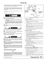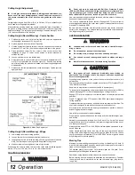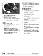
Operation
13
MAN1279 (15/04/2019)
Shredding
The cutter may be used to shred various crops including green manure, straw,
stubble, asparagus residue, corn stalks and similar crops in preparation for till-
ing. It may also be used to shred pruning in orchards, groves and vineyards.
Each shredding operation may require a different set-up. Start with front edge
of cutter high. Adjust up or down as necessary with attitude rod. Experiment
until you obtain the results you want.
When shredding attitude is set, check that the distance from the bottom rear
edge of the wing to the ground matches the bottom edge of the rear centre sec-
tion to the ground.
TRANSPORTING
■
Always raise unit and install transport locks before transporting.
Leak down or failure of mechanical or hydraulic system can cause equip-
ment to drop.
■
Always attach safety chain to tractor drawbar when transporting
unit.
■
Never exceed 40 km/h (25 mph) during transport.
■
Never allow riders on power unit or attachment.
■
Do not operate PTO during transport.
■
Do not operate or transport on steep slopes.
■
Do not operate or transport equipment while under the influence of
alcohol or drugs.
■
Watch for hidden hazards on the terrain during operation.
■
Stop power unit and equipment immediately upon striking an
obstruction. Turn off engine, remove key, inspect and repair any damage
before resuming operation.
■
Never allow children or untrained persons to operate equipment.
■
Do not allow bystanders in the area when operating, attaching,
removing, assembling, or servicing equipment.
■
Make sure spring-activated locking pin or collar slides freely and is
seated firmly in tractor PTO spline groove.
■
Always wear relatively tight and belted clothing to avoid getting
caught in moving parts. Wear sturdy, rough-soled work shoes and prote-
tive equipment for eyes, hair, hands, hearing, and head. Wear a respirator
or filter mask where appropriate.
■
When transporting, pay special attention to overhead power lines
and make sure that machine has sufficient clearance to pass.
■
Always comply with all state and local lighting and marking require-
ments.
Lock-Up
Always transport with wings and centre frame in the raised, locked position.
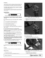
Wing Lock-Up
1.
Raise wing to the up position.
2.
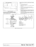
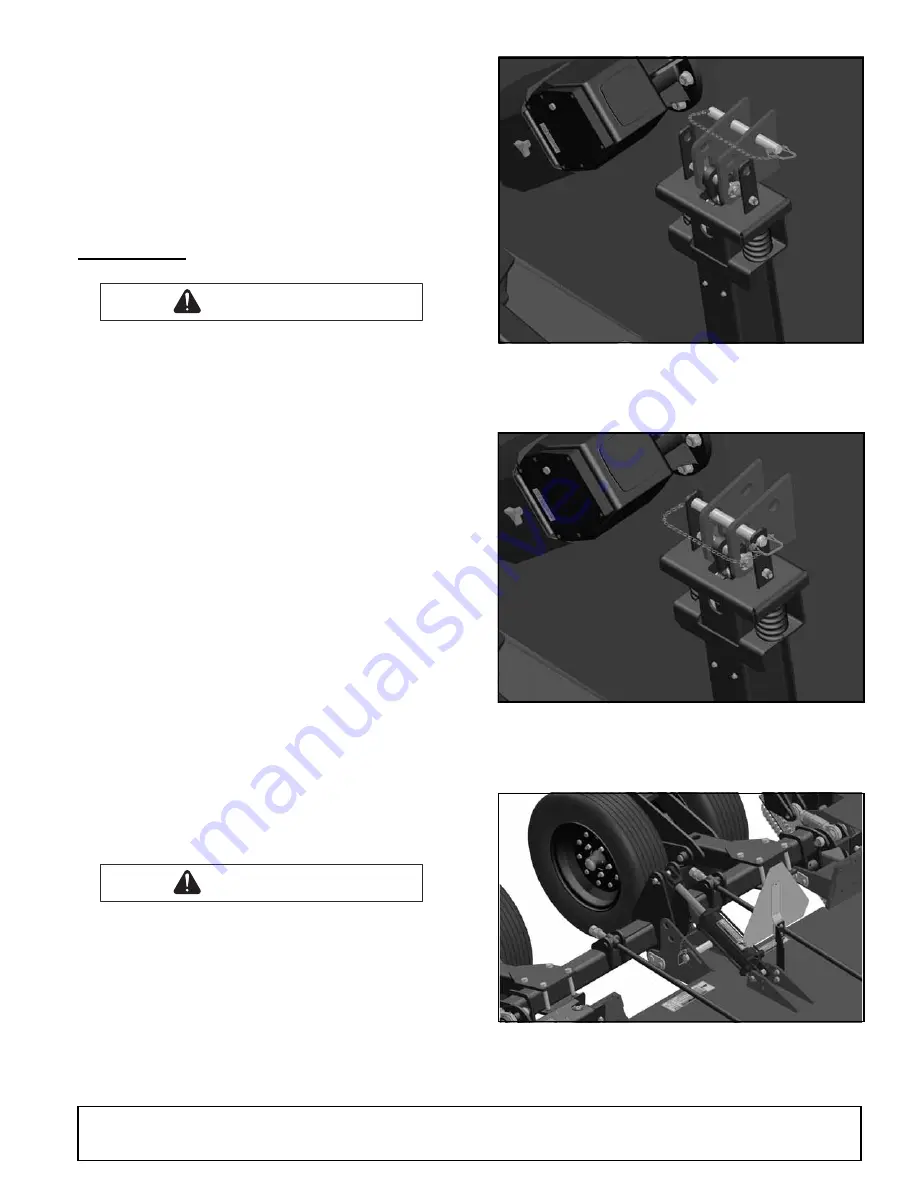
Remove klik pin and lock pin from storage position (Figure 2).
Figure 2
. Transport Lock Pin in Storage Position
3.
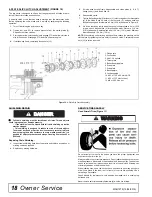
Place lock pin in lock position and secure with klik pin (Figure 3).
4.
Repeat steps 1 through 3 for opposite wing.
5.
Release pressure on cylinder so that wing is secured against lock pin
(Figure 3).
Figure 3
. Transport Lock Pin
Centre Section Lock-Up
1.
Raise cutter with hydraulic cylinder to maximum height.
2.
Remove klik pin and lock pin from storage position (Figure 4).
Figure 4
. Transport Lock Pin In Storage Position
3.
Place lock pin and klik pin in lock position and lower cutter against lock
pin. See Figure 5.
•
Upper hole provides higher transport height.
•
Middle hole provides narrow transport width.
WARNING
WARNING
CAUTION
CAUTION
Summary of Contents for BATWING BW20.50QE
Page 1: ...OPERATOR S MANUAL BATWING ROTARY CUTTER Rev 22 10 2019 BW20 50QE BW20 60QE BW20 70QE MAN1279...
Page 10: ...10 Declaration of Conformity MAN1279 15 04 2019...
Page 45: ...Common Components 45 MAN1279 15 04 2019 NOTES...
Page 46: ...46 50 Series Parts MAN1279 15 04 2019 CENTER FRAME ASSEMBLY BW20 50QE...
Page 50: ...50 50 Series Parts MAN1279 15 04 2019 WING CENTER GEARBOX ASSEMBLY BW20 50QE...
Page 55: ...50 Series Parts 55 MAN1279 15 04 2019 NOTES...
Page 56: ...56 60 Series Parts MAN1279 15 04 2019 CENTER FRAME ASSEMBLY BW20 60QE...
Page 60: ...60 60 Series Parts MAN1279 15 04 2019 WING CENTER GEARBOX ASSEMBLY BW20 60QE...
Page 66: ...66 70 Series Parts MAN1279 15 04 2019 CENTER FRAME ASSEMBLY BW20 70QE...
Page 70: ...70 70 Series Parts MAN1279 15 04 2019 WING CENTER GEARBOX ASSEMBLY BW20 70QE...
Page 90: ...10 Declaration of Conformity MAN1279 15 04 2019 10 D claration de conformit MAN1279 15 04 2019...


