Dealer Service
29
MAN1279 (15/04/2019)
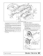
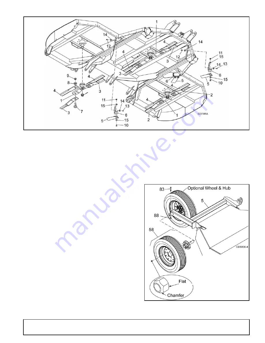
Figure 30
. Shredder Kit Installation
1.
Attach mounting bracket (6) to the front side of the front baffle and secure
with cap screws (12), hardened flat washers (14) and lock nuts (13). Do
not tighten hardware.
2.
Attach stationary blade (5) to mounting bracket (6) using two cap screws
(10), four hardened flat washers 915) and lock nuts (11). Blade should be
angled by using the first hole on the left side and the second hole on the
right side. Refer to Figure 29.
3.
Rotate crossbar and blades so stationary blade fits between the two
crossbar blades. Adjust mounting bracket (6) so the stationary blade (5)
is 25.4 mm (1 in.) below flat blade (4), Tighten all hardware. See Figure
29.
NOTE:
Stationary blade should be parallel to the rotating blades, point
toward the center of the gearbox and rear of cutter, and overlap rotating
blades approximately 101.6 mm (4 inches).
4.
Repeat steps to install stationary mounting bracket (6) and blade (5) to
the opposite wing.
Install Wing Wheel (Figure 31)
1.
Insert wheel hub into wing wheel yoke arms (5) and align holes.
2.
Secure into position using cap screw (83) and flanged lock nut (88).
3.
Attach wheel to hub using five lug nuts. Install the chamfered side of the
lug nut toward the inside for steel rim for pneumatic tires and rims.
Tighten to 115 N-m (85 lbs-ft). Check that tire air pressure is a maximum
of 2.78 bar (40 psi).
NOTE: Install the flat side of the nut toward the inside for solid tires
and aircraft tires (shown).
4.
Install optional dual wheel and hub to inside of wheel yoke arm.
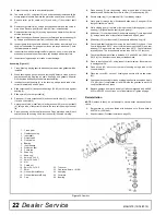
Figure 31
. Wing Wheel - Right
5. Wing wheel yoke arm, right
58. Wheel and hub
83. 1/2 NC x 3 HHCS GR5
88. 1/2 NC Flanged lock nut
Summary of Contents for BATWING BW20.50QE
Page 1: ...OPERATOR S MANUAL BATWING ROTARY CUTTER Rev 22 10 2019 BW20 50QE BW20 60QE BW20 70QE MAN1279...
Page 10: ...10 Declaration of Conformity MAN1279 15 04 2019...
Page 45: ...Common Components 45 MAN1279 15 04 2019 NOTES...
Page 46: ...46 50 Series Parts MAN1279 15 04 2019 CENTER FRAME ASSEMBLY BW20 50QE...
Page 50: ...50 50 Series Parts MAN1279 15 04 2019 WING CENTER GEARBOX ASSEMBLY BW20 50QE...
Page 55: ...50 Series Parts 55 MAN1279 15 04 2019 NOTES...
Page 56: ...56 60 Series Parts MAN1279 15 04 2019 CENTER FRAME ASSEMBLY BW20 60QE...
Page 60: ...60 60 Series Parts MAN1279 15 04 2019 WING CENTER GEARBOX ASSEMBLY BW20 60QE...
Page 66: ...66 70 Series Parts MAN1279 15 04 2019 CENTER FRAME ASSEMBLY BW20 70QE...
Page 70: ...70 70 Series Parts MAN1279 15 04 2019 WING CENTER GEARBOX ASSEMBLY BW20 70QE...
Page 90: ...10 Declaration of Conformity MAN1279 15 04 2019 10 D claration de conformit MAN1279 15 04 2019...

