Safety
5
BW15_SR (15/04/2019)
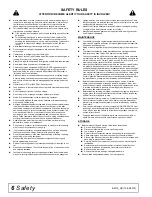
INSTALLATION
Hydraulics must be connected as instructed in this manual. Do not sub-
stitute parts, modify, or connect in any other way.
TRAINING
Safety instructions are important! Rear all attachment and power unit
manuals; follow all safety rules and safety decal information. (Replace-
ment manuals and safety decals are available from your dealer. To locate
your nearest dealer, check the Dealer Locator at www.WoodsEquip-
ment.eu, or call +32 10 301111 in Belgium.) Failure to follow instructions
or safety rules can result in serious injury or death.
If you do not understand any part of this manual and need assistance,
see your dealer.
Know your controls and how to stop engine and attachment quickly in an
emergency.
Operators must be instructed in and be capable of the safe operation of
the equipment, its attachments, and all controls. Do not allow anyone to
operate this equipment without proper instructions.
Keep hands and body away from pressurized lines. Use paper or card-
board, not hands or other body parts to check for leaks. Wear safety gog-
gles. Hydraulic fluid under pressure can easily penetrate skin and will
cause serious injury or death.
Make sure that all operating and service personnel know that if hydraulic
fluid penetrates skin, it must be surgically removed as soon as possible
by a doctor familiar with this form of injury or gangrene, serious injury, or
death will result.
CONTACT A PHYSICIAN IMMEDIATELY IF FLUID ENTERS SKIN OR
EYES, DO NOT DELAY.
Never allow children or untrained persons to operate equipment.
PREPARATION
Check that all hardware is properly installed. Always tighten to torque
chart specifications unless instructed otherwise in this manual.
Air in hydraulic systems can cause erratic operation and allows loads or
equipment components to drop unexpectedly. When connecting equip-
ment or hoses or performing any hydraulic maintenance, purge any air in
hydraulic system by operating all hydraulic functions several times. Do
this before putting into service or allowing anyone to approach the equip-
ment.
Make sure all hydraulic hoses, fittings, and valves are in good condition
and not leaking before starting power unit or using equipment. Check and
route hoses carefully to prevent damage. Hoses must not be twisted,
bent sharply, kinked, frayed, pinched, or come into contact with any mov-
ing parts. Operate moveable components through full operational range
to check clearances. Replace any damaged hoses immediately.
After connecting hoses, check that all control lever positions function as
instructed in the Operator's Manual. Do not put into service until control
lever and equipment movements are correct.
Set tractor hydraulic relief valve at 2500 psi (170 bars) (17,000 kPa) to
prevent injury and equipment damage due to hydraulic system failure.
Your dealer can supply original equipment hydraulic accessories and
repair parts. Substitute parts may not meet original equipment specifica-
tions and may be dangerous.
Always wear relatively tight and belted clothing to avoid getting caught in
moving parts. Wear sturdy, rough-soled work shoes and protective equip-
ment for eyes, hair, hands, hearing, and head; and respirator or filter
mask where appropriate.
Make sure attachment is properly secured, adjusted, and in good operat-
ing condition.
Make sure spring-activated locking pin or collar slides freely and is
seated firmly in tractor PTO spline groove.
Make sure driveline guard tether chains are attached to the tractor and
equipment as shown in the pamphlet that accompanies the driveline.
Replace if damaged or broken. Check that driveline guards rotate freely
on driveline before putting equipment into service.
Before starting power unit, check all equipment driveline guards for dam-
age. Replace any damaged guards. Make sure all guards rotate freely on
all drivelines. If guards do not rotate freely on drivelines, repair and
replace bearings before putting equipment into service.
Power unit must be equipped with ROPS or ROPS cab and seat belt.
Keep seat belt securely fastened. Falling off power unit can result in
death from being run over or crushed. Keep foldable ROPS system in
“locked up” position at all times.
Remove accumulated debris from this equipment, power unit, and engine
to avoid fire hazard.
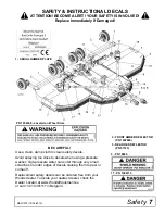
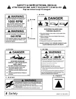
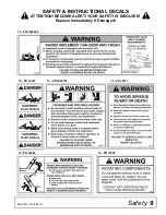
Make sure all safety decals are installed. Replace if damaged. (See
Safety Decals section for location.)
Make sure shields and guards are properly installed and in good condi-
tion. Replace if damaged.
Do not put this equipment into service unless all side skids are properly
installed and in good condition. Replace if damaged.
A minimum 20% of tractor and equipment weight must be on the tractor
front wheels when attachments are in transport position. Without this
weight, front tractor wheels could raise up resulting in loss of steering.
The weight may be attained with front wheel weights, ballast in tires, front
tractor weights or front loader. Weigh the tractor and equipment. Do not
estimate.
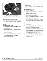
Inspect and clear area of stones, branches, or other hard objects that
might be thrown, causing injury or damage.
Connect PTO driveline directly to power unit PTO shaft. Never use
adapter sleeves or adapter shafts. Adapters can cause driveline failures
due to incorrect spline or incorrect operating length and can result in per-
sonal injury or death.
TRANSPORTATION
Power unit must be equipped with ROPS or ROPS cab and seat belt.
Keep seat belt securely fastened. Falling off power unit can result in
death from being run over or crushed. Keep foldable ROPS system in
“locked up” position at all times.
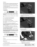
Always raise unit and install transport locks before transporting. Leak
down or failure of mechanical or hydraulic system can cause equipment
to drop.
Always attach safety chain to tractor drawbar when transporting unit.
Always comply with all state and local lighting and marking requirements.
Never allow riders on power unit or attachment.
Do not operate PTO during transport.
Do not operate or transport on steep slopes.
Do not operate or transport equipment while under the influence of alco-
hol or drugs.
The maximum transport speed for towed and semi-mounted machines is
40 km/h (24.85 mph). Regardless of the maximum speed capability of the
towing tractor, do not exceed the implement’s maximum transport speed.
Doing so could result in:
●
Loss of control of the implement and tractor
●
Reduced or no ability to stop during braking
●
Implement tire failure
●
Damage to the implement or its components.
Use additional caution and reduce speed when under adverse surface
conditions, turning, or on inclines.
Never tow this implement with a motor vehicle.
When transporting, pay special attention to overhead power lines and
make sure the machine has sufficient clearance to pass.
OPERATION
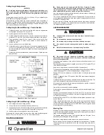
Stop power unit and equipment immediately upon striking an obstruction.
Turn off engine, set parking brake, remove key, inspect, and repair any
damage before resuming operation.
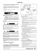
Do not allow bystanders in the area when operating, attaching, removing,
assembling, or servicing equipment.
Stay away from the machinery during a thunderstorm. Do not operate
machine during a thunderstorm. If lightning from a thunderstorm strikes
during operation, remain in the tractor cab. Do not make contact with the
ground of objects outside the machine. Do not leave the cab until the
storm has passed.
Safety is a primary concern in the design and manufacture of our
products. Unfortunately, our efforts to provide safe equipment can be
wiped out by an operator’s single careless act.
In addition to the design and configuration of equipment, hazard con-
trol and accident prevention are dependent upon the awareness, con-
cern, judgement, and proper training of personnel involved in the
operation, transport, maintenance, and storage of equipment.
It has been said, “The best safety device is an informed, careful oper-
ator.” We ask you to be that kind of operator.
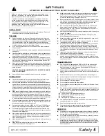
SAFETY RULES
ATTENTION! BECOME ALERT! YOUR SAFETY IS INVOLVED!
Summary of Contents for BATWING BW20.50QE
Page 1: ...OPERATOR S MANUAL BATWING ROTARY CUTTER Rev 22 10 2019 BW20 50QE BW20 60QE BW20 70QE MAN1279...
Page 10: ...10 Declaration of Conformity MAN1279 15 04 2019...
Page 45: ...Common Components 45 MAN1279 15 04 2019 NOTES...
Page 46: ...46 50 Series Parts MAN1279 15 04 2019 CENTER FRAME ASSEMBLY BW20 50QE...
Page 50: ...50 50 Series Parts MAN1279 15 04 2019 WING CENTER GEARBOX ASSEMBLY BW20 50QE...
Page 55: ...50 Series Parts 55 MAN1279 15 04 2019 NOTES...
Page 56: ...56 60 Series Parts MAN1279 15 04 2019 CENTER FRAME ASSEMBLY BW20 60QE...
Page 60: ...60 60 Series Parts MAN1279 15 04 2019 WING CENTER GEARBOX ASSEMBLY BW20 60QE...
Page 66: ...66 70 Series Parts MAN1279 15 04 2019 CENTER FRAME ASSEMBLY BW20 70QE...
Page 70: ...70 70 Series Parts MAN1279 15 04 2019 WING CENTER GEARBOX ASSEMBLY BW20 70QE...
Page 90: ...10 Declaration of Conformity MAN1279 15 04 2019 10 D claration de conformit MAN1279 15 04 2019...


