


Electrical Information
Form #1014
doc100206
A-8
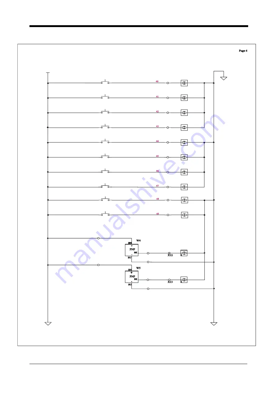
DIAGRAM (6 OF 12)
+24
C0
I
3
4
Ps11
Left
forward
Joystick
I
3
4
Ps12
I
3
4
I
3
4
I
3
4
I
3
4
I
3
4
I
3
4
X0
X1
X2
X3
X4
X5
X6
X7
X10
X11
X12
X13
53
53
51
X0
X1
X2
X3
X4
X5
X6
X7
C0
C0
C0
C1
C1
C1
C1
I
3
4
I
3
4
X10
X11
C2
C2
C2
C2
+24 DC
51
Left Joystick backward
Right Joystick forward
Right Joystick backward
Right Joystick right
Right Joystick left
Left
right
Joystick
Left
left
Joystick
Left
upper button
Joystick
Right
upper button
Joystick
Ps13
Ps14
Ps15
Ps16
Ps17
Ps18
Ps19
Ps20
25
53
53
53
53
53
Rear Limit Switch
Front Limit Switch


