background image

 
cyber

®

 simco

®

 drive 2 operating manual


en-4 

5022-D057946 

Revision: 02 

1  About this manual 

This manual contains information which is necessary for the safe use of the drive amplifier 

cyber

® 

simco

®

 drive 2

, hereafter known as drive amplifier. 

The operator must ensure that this operating manual is read through by all persons assigned 
to install, operate, or maintain the drive amplifier, and that they fully comprehend it. 
If this manual is supplied with amendment sheets (e.g. for special applications), then the 
information in the amendment is valid. Contradictory specifications in this manual are 
therefore void. 
The operator must ensure that this operating manual is read through by all persons assigned 
to install, operate, or maintain the drive system, and that they fully comprehend its content. 
Store this manual within reach of the drive amplifier. 
Inform colleagues who work in the area around the machine about the 

safety instructions


so that no one sustains injuries. 
The original was prepared in German, all other language versions are translations of the 
original instructions. 
 

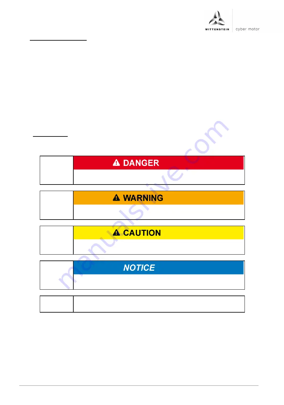
1.1  Signal words 

The following signal words are used to indicate hazards, things that are forbidden and 
important information: 


This signal word indicates an imminent danger that will cause 
serious injuries or even death. 


This signal word indicates a potential hazard that could cause 
serious injuries and even death. 


This signal word indicates a potential hazard that could cause 
minor or serious injuries. 


This signal word indicates a potential hazard that could lead to 
property damage. 


A note without a signal word indicates application hints or 
especially important information for handling the product. 


Summary of Contents for Cyber Simco Drive 2

Page 1: ...5022 D057946 Revision 02 cyber simco drive 2 Operating manual ...

Page 2: ......

Page 3: ... questions about installation commissioning or optimization please contact our support hotline WITTENSTEIN cyber motor GmbH support hotline Tel 49 0 79 31 493 14800 In the event of technical malfunctions contact us at the following address WITTENSTEIN cyber motor GmbH Customer Service Walter Wittenstein Str 1 D 97999 Igersheim Tel 49 0 79 31 493 15900 Email service wittenstein cyber motor de Copyr...

Page 4: ... 17 5 2 6 IP65 Environmental conditions for vibration shock 17 5 3 Device version IP20 central SIM20xxD CC 18 5 3 1 IP20 Dimensions 18 5 3 2 IP20 mounting options 19 5 3 3 IP20 disassembly 19 5 3 4 IP20 installation space 19 5 3 5 IP20 Environmental conditions for vibration shock 19 5 3 6 IP20 mounting position 20 5 3 7 IP20 ventilation cooling 20 6 Electrical installation 21 6 1 Safety instructio...

Page 5: ... 7 3 3 LED codes NS 46 8 Maintenance and disposal 48 8 1 Maintenance work 48 8 1 1 Maintenance 48 8 1 2 Cleaning 48 8 1 3 Visual inspection 48 8 1 4 Repairs 48 8 2 Disposal 48 9 Appendix 48 9 1 Tightening torques 48 10 STO safety function instructions 49 10 1 Installation space 49 10 2 STO wiring 49 10 3 Important information for STO 49 10 4 Intended use of STO 50 10 5 Improper use of STO 50 10 6 ...

Page 6: ...ystem and that they fully comprehend its content Store this manual within reach of the drive amplifier Inform colleagues who work in the area around the machine about the safety instructions so that no one sustains injuries The original was prepared in German all other language versions are translations of the original instructions 1 1 Signal words The following signal words are used to indicate h...

Page 7: ...of the safety information Safety information in this manual has been structured according to the following template Explanatory text shows the consequences of disregarding this information Instructive text uses direct address to indicate what to do 1 4 Information symbols The following information symbols are used Indicates an action to be performed Indicates the results of an action Provides addi...

Page 8: ... the requirements of this documentation Deviations and nonconformity with requirements in this documentation mean that the drive amplifier may not fulfill statutory requirements under certain circumstances The drive amplifier is in conformity with the following directives Machinery Directive 2006 42 EC Electromagnetic Compatibility EMC 2014 30 EU RoHS Directive 2011 65 EU In terms of interference ...

Page 9: ...ately use an UL listed fuse with an lower I t rating of 25 kA and an Ip value of 10 5 kA Tightening torque for factory wiring terminals 0 5 Nm These products are intended for operation within circuits not connected directly to the supply mains galvanically isolated from the supply i e on transformer secondary This EUT is for use in non hazardous locations operated by qualified personell skilled in...

Page 10: ...ne the drive amplifier may be put to use only for its intended usage see chapter 2 6 Intended use and in a technically flawless and safe state 2 5 Personnel Only qualified technicians who have read and understood this manual may carry out work on the drive amplifier Information on the drive amplifier in particular the safety instructions must be accessible to all persons who work with the drive am...

Page 11: ...r as much as possible by taking appropriate action Nonetheless known residual risks must be taken into account for the risk assessment of machines and systems 2 8 1 Prohibited movements Prohibited movements can be caused by The failure or shut down of safety monitoring Software nonconformity in associated controllers or bus systems Nonconformity during parameterization Nonconformity in wiring Limi...

Page 12: ... cables or plugs Electrical connection work refers to all work on the electrical circuit for which faults and associated hazards cannot be excluded Connecting the power and signal supply lines under voltage is not permitted and can lead to machine damage serious injury or even death Make sure that the power supply unit is always in a voltage free state before connecting Separation of the power and...

Page 13: ...code DMC O Ambient temperature G Bus interface P Manufacturer H Customer material number Q Service portal code I Calendar week and year of production R Serial number Table 1 IP20 name plate Designation Designation A Product designation J Intermediate circuit voltage UD B Data matrix code DMC K Maximum current Imax C Type code L Continuous stall current In D Material number M PWM frequency E Bus in...

Page 14: ...circuit voltage V DC 12 60 12 60 Logic power supply V DC 12 60 12 60 Current consumption of logic supply mA DC 250 250 Nominal output current of the output stage Aeff 7 51 151 Peak output current of the output stage for 5 s Aeff 15 30 Clock frequency of the output stage kHz 16 16 Electrical rotary field frequency Hz 0 1000 0 1000 Table 3 Electrical data 1 In the case of the mounting position descr...

Page 15: ...uitive startup and diagnosis is possible using the PC based MotionGUI 2 graphic user interface 3 4 1 Integrated safety Comprehensive functions to protect the drive amplifier such as overvoltage overcurrent short circuit or ground fault Temperature monitoring of the drive amplifier motor or optionally the gearbox 3 4 2 Digital regulation Digital d q current controller PI with a sampling rate of up ...

Page 16: ...pF m Resolver line 20 m 120 pF m Table 4 Cabling and wiring Further requirements regarding TÜV NRTL are listed in chapter 2 1 2 Conformity with TÜV NRTL 3 6 STO safety function The STO safety function Safe Torque Off is used for safe torque shutdown and to reliably protect drives from restarting The drive amplifier is fitted with a two channel STO function as standard in the basic model Instructio...

Page 17: ... the box 4 2 Transport Transportation only in original packaging by qualified personnel Avoid hard impacts and vibrations Transport temperature 20 60 C max 20 K hour fluctuation Transport air humidity Relative humidity max 95 non condensing If the packaging is damaged check the drive amplifier for visible damage Contact the responsible shipping company The drive system contains components that are...

Page 18: ...rive amplifiers During installation in a control cabinet sufficient ventilation must be provided The operation of drive amplifiers exposed to condensation is not permitted The drive system may only be assembled with the power disconnected Systems that are electrically connected must be properly secured so they cannot be switched back on and warning signs must be put up Assembly may only be perform...

Page 19: ...ing position Any mounting position can be selected 5 2 5 IP65 ventilation cooling Sufficient convection for cooling of the drive amplifier must be ensured at the installation location To avoid overheating closed installation sites with low volume flow are not suitable for installation of the drive amplifier The drive amplifier is to be mounted on a flat metallic surface 5 2 6 IP65 Environmental co...

Page 20: ...erating manual en 18 5022 D057946 Revision 02 5 3 Device version IP20 central SIM20xxD CC 5 3 1 IP20 Dimensions Mechanical data Weight g 360 Length mm 186 95 Width mm 51 3 Depth without plug mm 56 95 Table 6 IP20 Dimensions ...

Page 21: ... 3 For tightening torques see chapter 9 1 Tightening torques 5 3 3 IP20 disassembly The drive amplifier is disassembled from the top hat rail by pushing downwards and removing the drive amplifier See following figure 5 3 4 IP20 installation space The central variant of the drive amplifier is designed for installation in the control cabinet 5 3 5 IP20 Environmental conditions for vibration shock Th...

Page 22: ...ances must be selected according to the following illustration 5 3 7 IP20 ventilation cooling Ensure that there is sufficient forced air circulation in the closed control cabinet The airflow at the bottom air intake of the device has to be at least 0 8 m s so that the device is sufficiently cooled under standard operational conditions ...

Page 23: ...ns which are not being used must be fitted with dummy connectors which are included in delivery Observe the separate instructions for the STO safety function see chapter 10 STO safety function instructions 6 2 Installing the electrical connections Electrically live components may result in electric shocks if touched and can cause serious injuries and even death Observe the five safety rules of ele...

Page 24: ...rs or supply voltage sources having only basic installation are not permissible The use of unsuitable power adapters not in SELV PELV design can lead to dangerously high voltages in the event of a fault which could lead to dangerous electric shocks resulting in injuries or death The drive amplifier can generate a voltage of up to 60 VDC at the power adapter terminals for power supply when operatin...

Page 25: ...coded X6 Resolver interface M12 8 pin female A coded M12 8 pin male A coded X7 Encoder interface M12 8 pin female A coded M12 8 pin male A coded X8 Motor connection Intercontec itec 915 15 pin female Intercontec itec 915 15 pin male 6 4 2 IP65 Connection diagram The following illustrations show the key connection diagrams of the drive amplifier when supplied with SELV and PELV power supply units F...

Page 26: ...ieldbus OUT M12 4 5 pin X5 1 DIN1 Digital inputs outputs 2 DIN2 3 DIN3 4 DIN4 M12 8 pin PLC outputs switches or PLC inputs actuators 24VDC 5 DOUT1 6 DOUT2 7 VCC24 8 GND 24VDC X6 Resolver M12 8 pin 1 COS 2 COS 3 SIN 4 SIN 5 REF 6 REF 7 N C 8 N C Power supply Battery 12 60 VDC 48 VDC nom GND F1 X7 1 GND Encoder 2 VCC 3 CLK 4 CLK 5 DATA 6 DATA 7 A 8 A M12 12 pin 9 B 10 B 11 Z 12 Z Encoder emulation X...

Page 27: ...TEMP 10 TEMP 11 BRAKE 12 BRAKE M F U V W X5 1 DIN1 Digital inputs outputs 2 DIN2 3 DIN3 4 DIN4 M12 8 pin PLC outputs switches or PLC inputs actuators 24VDC 5 DOUT1 6 DOUT2 7 VCC24 8 GND 24VDC X6 Resolver M12 8 pin 1 COS 2 COS 3 SIN 4 SIN 5 REF 6 REF 7 N C 8 N C Power supply 12 60 VDC 48 VDC nom GND F1 Safety control DOUT DOUT GND Optional power supply unit 12 60 VDC 24 VDC nom GND F2 12 60VDC 9 B ...

Page 28: ...and the housing within the device Figure Pin no Signal name Function Input output A DCBus Intermediate circuit voltage Input B DCBus Intermediate circuit voltage Input C CHOPPER External brake resistance Output FE FE Functional earth Functional earth 1 Logic Logic supply Input 2 N C 3 STO Safe torque off input Input 4 N C 5 STO GND STO ground reference Input Plug type on drive amplifier Interconte...

Page 29: ...e amplifier M12 5 pin female A coded at X2 Connection Feature Unit Minimum value Nominal value Maximum value Baud rate kbaud 100 500 1000 6 5 3 X3 CANopen fieldbus interface input The CAN ground reference is identical to the logic ground reference Figure Pin no Signal Function 1 Shield Screen 2 N C 3 CAN_GND CAN ground reference 4 CAN_H CAN High 5 CAN_L CAN Low Plug type on drive amplifier M12 5 p...

Page 30: ...D Transmit Data 4 RD Receive Data Plug type on drive amplifier M12 4 pin female D coded at X2 and X3 Connection Feature Unit Minimum value Nominal value Maximum value Transmission speed MBit s 100 6 5 5 X4 USB diagnostic interface Figure Pin no Signal Function Input output 1 5V Supply voltage Input 2 DM Data Input output 3 DP Data Input output 4 GND Ground reference Plug type on drive amplifier M1...

Page 31: ...s are short circuit proof Figure Pin no Signal name Function Input output 6 DIN1 Digital input 1 Input 1 DIN2 Digital input 2 Input 8 DIN3 Digital input 3 Input 2 DIN4 Digital input 4 Input 7 GND Ground reference 3 DOUT1 Digital output 1 Output 4 DOUT2 Digital output 2 Output 5 VCC24 Digital output supply Input Plug type on drive amplifier M12 8 pin male A coded Connection Feature Unit Minimum val...

Page 32: ... Via the encoder interface X7 fully digital encoder systems with the protocols EnDat 2 2 and BISS C can be evaluated The encoder interface has a 5 V power supply secured with a self resetting fuse with a current rating of 500 mA Figure Pin no Signal name Function Input output 1 GND Ground reference Output 2 VCC Encoder power supply Output 3 CLOCK Clock output Output 4 CLOCK Clock output inverted O...

Page 33: ...Motor phase W Output 1 GND Ground reference 2 VCC5 Encoder voltage 5 VDC Output 3 CLOCK Clock signal Output 4 CLOCK Clock signal inverted Output 5 DATA Data signal Input 6 DATA Data signal inverted Input 7 Z Z trace 8 Z Z trace 9 TEMP Motor temperature sensor Input 10 TEMP Motor temperature sensor Input 11 BRAKE Holding brake Output 12 BRAKE Holding brake Output Plug type on drive amplifier Interc...

Page 34: ...iagrams of the drive amplifier when supplied with SELV and PELV power supply units For applications in driverless transport systems DTS the standard DIN EN 1175 1 VDE 0117 1 2011 06 must be applied If simco drive 2 is to be used in a DTS application the wiring illustrated in the following must be used due to missing galvanic isolation between logic and power In this respect simco drive 2 is fully ...

Page 35: ...xx xxxx X8 1 DOUT 2 Digital inputs outputs 2 DOUT 1 3 DIN 4 4 DIN 3 5 DIN 2 6 DIN 1 7 GND 8 24VDC Dinkle 0225 3708L X9 Temp Brake PLC outputs switches or PLC inputs actuators 24VDC PLC Fieldbus Master Power supply Battery 12 60 VDC 48 VDC nom GND M U V W PC MotionGUI 2 USB X1 1 DC Bus Supply 2 DC Bus 3 CHOPPER 4 FE Dinkle 5EHDVC 04PL 6 REF 7 N C 8 N C 9 N C 9 B 10 B 11 Z 12 Z 13 N C 14 N C 15 N C ...

Page 36: ... 60 VDC 48 VDC nom GND Optional auxiliary supply 12 60 VDC 24 VDC nom GND F2 PC MotionGUI 2 USB X1 1 DC Bus Supply 2 DC Bus 3 CHOPPER 4 FE Dinkle 5EHDVC 04PL 6 REF 7 N C 8 N C 9 N C 9 B 10 B 11 Z 12 Z 13 N C 14 N C 15 N C F 12 60 VDC F1 Encoder emulation DOUT DOUT GND Safety control A type X8 Digital inputs outputs Dinkle 0225 3708L X9 Temp Brake PLC outputs switches or PLC inputs actuators M U V ...

Page 37: ... be ensured that the top hat rail is connected to the control cabinet s functional ground with sufficiently low impedance If the drive amplifier is not sufficiently grounded this may cause radio interference leading to non conformity with the EC EMC Directive This can result in malfunctions in the drive amplifier and other electronic systems 6 6 4 IP20 shield connection The figure shows the connec...

Page 38: ...oss section AWG 24 26 Stripping length 8 mm Plug type X2 at Dinkle 0181 A303 Permissible wire cross section AWG 24 12 Stripping length 8 mm Connection Feature Unit Minimum value Nominal value Maximum value Logic Voltage V DC 12 24 60 Current mA DC 200 STO Voltage V DC 12 24 60 Current mA DC 80 DCBus Voltage V DC 12 48 60 Current A DC 301 152 Chopper Voltage V DC 563 Current A DC 94 15 für 15s 4 25...

Page 39: ... SIN Sine trace S2 Input 4 SIN Sine trace S4 Input 5 REF Reference trace R1 Output 6 REF Reference trace R2 Output 7 N C 8 N C 9 N C Plug type on drive amplifier D Sub 9 pin female Connection Feature Unit Minimum value Nominal value Maximum value Reference trace Excitation frequency kHz 10 Output voltage Vpk 4 5 5 5 Output current mA 30 Sine cosine Input resistance kOhm 100 Input voltage Vpk 2 5 5...

Page 40: ...inverted Output 5 DATA Data channel Input 6 DATA Data channel inverted Input 7 A Encoder emulation A Output 8 A Encoder emulation A Output 9 B Encoder emulation B Output 10 B Encoder emulation B Output 11 Z Encoder emulation Z Output 12 Z Encoder emulation Z Output 13 N C 14 N C 15 N C Plug type on drive amplifier D Sub 15 pin female Connection Feature Unit Minimum value Nominal value Maximum valu...

Page 41: ...J8 N C Plug type on drive amplifier LAN RJ45 Connection Feature Unit Minimum value Nominal value Maximum value Baud rate kbaud 100 500 1000 6 6 10 X6 X7 Fieldbus interface EtherCat PROFINET EtherNet IP and SERCOS III The signals are galvanically isolated from the logic and power of the drive Figure Pin no Signal name Function J1 RD Receive Data J2 RD Receive Data J3 TD Transmit Data J4 N C J5 N C ...

Page 42: ...d reference 3 DIN1 Digital input 1 Input 4 DIN2 Digital input 2 Input 5 DIN3 Digital input 3 Input 6 DIN4 Digital input 4 Input 7 DOUT1 Digital output 1 Output 8 DOUT2 Digital output 2 Output Plug type on drive amplifier Dinkle 0225 3708L 8 pin Connection Feature Unit Minimum value Nominal value Maximum value DINx Input voltage V DC 20 24 28 Input current mA DC 3 4 5 Input resistance kOhm 5 6 Samp...

Page 43: ...type X9 Dinkle 0159 0304 Permissible wire cross section AWG 24 26 Stripping length 8 mm Plug type X10 on Dinkle 0181 A303 Permissible wire cross section AWG 24 12 Stripping length 8 mm Tightening torque 0 5 0 6 Nm the tightening torque must be 0 5 Nm to conform to the UL requirement Connection Feature Unit Minimum value Nominal value Maximum value PHASE_x Current Aeff 151 7 52 301 152 BRAKE Voltag...

Page 44: ...iance are listed in chapter 2 1 2 6 7 2 Fuses on device version central IP20 The power supplies are to be secured with the fuses specified in the table Fuses Logic supply F2 X1 pin 1 Fuse or similar with max 4 AT Power supply F1 X2 pin 1 Fuse or similar with max 16 AT Brake chopper F3 X2 pin 3 Fuse or similar with max 10 AT Further requirements regarding NRTL compliance are listed in chapter 2 1 2...

Page 45: ...appropriate action so that unforeseen movements cannot lead to personal injury or property damage Only technicians with extensive experience with electrical and electronic systems and drive technology may start up the drive amplifier 7 2 Startup software For parameterization and startup of the drive the startup software MotionGUI 2 is available as well as an interactive html based guide The startu...

Page 46: ...status and fault messages on the drive amplifier DS MS NS in the colors green and red are available LED EtherCAT Ethernet IP PROFINET DS Drive Status Drive Status Drive Status MS RUN LED EtherCAT Drive Statemachine Module State System Failure NS ERR LED EtherCAT Error State Fieldbus State Bus Failure Table 7 Displays on the drive system ...

Page 47: ...stage is disabled Flash Yellow Green Drive amplifier is in warning state and output stage is enabled Constant Green Drive amplifier is in functional state and output stage is enabled Flash Red Green Drive amplifier is in Firmware Update state Table 8 LED codes DS 7 3 2 LED codes MS LED MS is dependent on the bus system type EtherCAT LED MS indicates the EtherCAT state machine state Status LED LED ...

Page 48: ...tem failure Status LED LED MS Meaning Off The device has no error or has no power supply or is defective Flash Red 1 Hz 3 s DCP signal service is initiated via the bus Constant Red Watchdog timeout channel generic or extended diagnosis present system error Table 11 LED codes MS PROFINET 7 3 3 LED codes NS LED NS is dependent on the bus system type EtherCAT LED NS indicates the error state Status L...

Page 49: ...P connection is active Flash Red An IP address is configured but the timeout limit was exceeded Constant Red The bus module has detected that its IP address is already in use Constant Green The bus has an IP address ant at least one CIP connection is active without timeout Table 13 LED codes NS Ethernet IP PROFINET LED NS BF indicates the bus failure Status LED LED NS Meaning Off The device has no...

Page 50: ...s The drive amplifier may only be repaired by the manufacturer Opening the drive amplifiers voids the warranty and safety according to the specified standards is no longer ensured 8 2 Disposal In accordance with WEEE 2002 96 EC directive we take back old equipment for proper disposal as long as the transport costs are paid by the sender 9 Appendix 9 1 Tightening torques Property class Tightening t...

Page 51: ...49 1 2015 10 1 Installation space A drive amplifier in protection class IP20 design should be installed in a space that will ensure reliable operation of the drive amplifier The installation space must meet the requirements of protection class IP54 at least 10 2 STO wiring In the case of single channel control if the wiring for the STO signals is situated outside a control cabinet it must be route...

Page 52: ...long interruptions in operation In such cases the entire machine or system should be de energized and secured at the main switch 2 Emergency stop situations In emergency stop situations the power supply must be cut off by a line contactor with emergency stop pushbutton 10 6 Technical data and STO pin assignment STO input Data STO inactive input voltage 12 60 VDC STO active input voltage Open Input...

Page 53: ...7946 en 51 deutsch english français italiano español 日本語 10 7 2 STO device version IP20 central SIM20xxD CC SIL 2 category 3 PLd SIL 3 category 4 PLe SIL 2 Cat 3 PLd Safety Unit X2 GND 3 STO GND 2 STO 24V SIL 3 Cat 4 PLe Safety Unit X2 3 STO GND 2 STO 24V GND ...

Page 54: ... channel control of the STO safety function the STO and STO GND shutdowns are switched separately by two outputs of a safety control STO 24 V status STO GND status Motor torque possible Open Open No 24 VDC 0 VDC Yes When wiring the STO inputs inside an installation space make sure that both the wiring used and the installation space itself meet the requirements of EN 60204 1 If the wiring is outsi...

Page 55: ...rely locked mechanically as well e g with a suitable holding brake If the STO function is actuated during operation the drive will coast to a stop in an uncontrolled manner Controlled braking of the drive will not be possible Danger from uncontrolled movement 10 9 Functional check The STO function must be checked at initial startup after any work on the system s wiring and after replacing one or m...

Page 56: ......

Reviews: