SmartPAC PRO User Manual
1143100
Chapter 2 – Installing SmartPAC PRO
71
10.
Plug the connector(s) back into its socket.
11.
To connect the relays to your equipment, use connectors TB302 and TB303.
Specific connections depend on the type of relay you use. For 120 VAC relays, you can connect
wires from your equipment to “C” and either the N/O (normally open)or N/C (normally closed)
side of the relay
All solid state relays work only when the C and the N/O terminals are connected. Polarity must be
correct for DC solid state relays (refer to Table 2-10.)
Table 2-10
. Connections to Relays
Module
How To Connect
Type
Electro-mechanical
Relay
One wire to C, one wire to N/O or N/C, polarity does not
matter
SPDT
DC Solid State
– to C, + to N/O
SPST
AC Solid State
One wire to C, one wire to N/O, polarity does not matter
SPST
WARNING
INCORRECT SUPPRESSOR INSTALLATION MAY CAUSE RELAYS TO REMAIN ENERGIZED
Ensure that suppressors are correctly installed. They must not be installed across the relay
contacts inside the ProCamPAC Output enclosure. If a suppressor is installed across the relay
contacts and it fails shorted, the equipment controlled by that relay will remain energized.
Failure to comply with these instructions could result in death or serious injury.
12.
To reduce electrical noise and to extend the life of the relays, do the following:
AC loads:
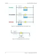
Install arc suppressors across each inductive load (motors, coils, etc.) that is connected to a cam
relay (see Figure 2-15). Suppressors are supplied with each relay. Install the suppressors across
the load or as close to the load as possible. Attach suppressors by connecting leads across existing
terminals or junction points.
DC loads:
Install a diode across each DC load, (see Figure 2-16)
Summary of Contents for SmartPAC PRO
Page 1: ......
Page 2: ......
Page 4: ......
Page 6: ......
Page 20: ......
Page 22: ......
Page 24: ......
Page 42: ...1143100 SmartPAC PRO User Manual 42 Chapter 1 Introduction to SmartPAC PRO ...
Page 142: ...1143100 SmartPAC PRO User Manual 142 Chapter 4 SmartPAC PRO Program Mode ...
Page 200: ...1143100 SmartPAC PRO User Manual 200 Chapter 6 Using DiProPAC Die Protection Optional ...
Page 222: ...1143100 SmartPAC PRO User Manual 222 Chapter 7 ProCamPAC Instructions ...
Page 254: ...1143100 SmartPAC PRO User Manual Appendix C SmartView Remote Viewing and E mail Setup 254 ...
Page 280: ...SmartPAC PRO User Manual 1143100 280 Appendix C Reporting Downtime and Scrap to SFC ...
Page 290: ...SmartPAC PRO User Manual 1143100 290 Index Y yellow fault 232 yellow sensor 169 ...
Page 292: ......
Page 294: ......
Page 296: ......
Page 298: ......
Page 300: ......
Page 301: ......
Page 302: ......
Page 303: ......
Page 304: ......
Page 305: ......
Page 306: ......
Page 307: ......
Page 308: ......
Page 309: ......
Page 310: ......
Page 311: ......
Page 312: ......
Page 313: ......
Page 314: ......
Page 315: ......
Page 316: ......
Page 317: ......
Page 318: ......

